是德科技 | KEYSIGHT
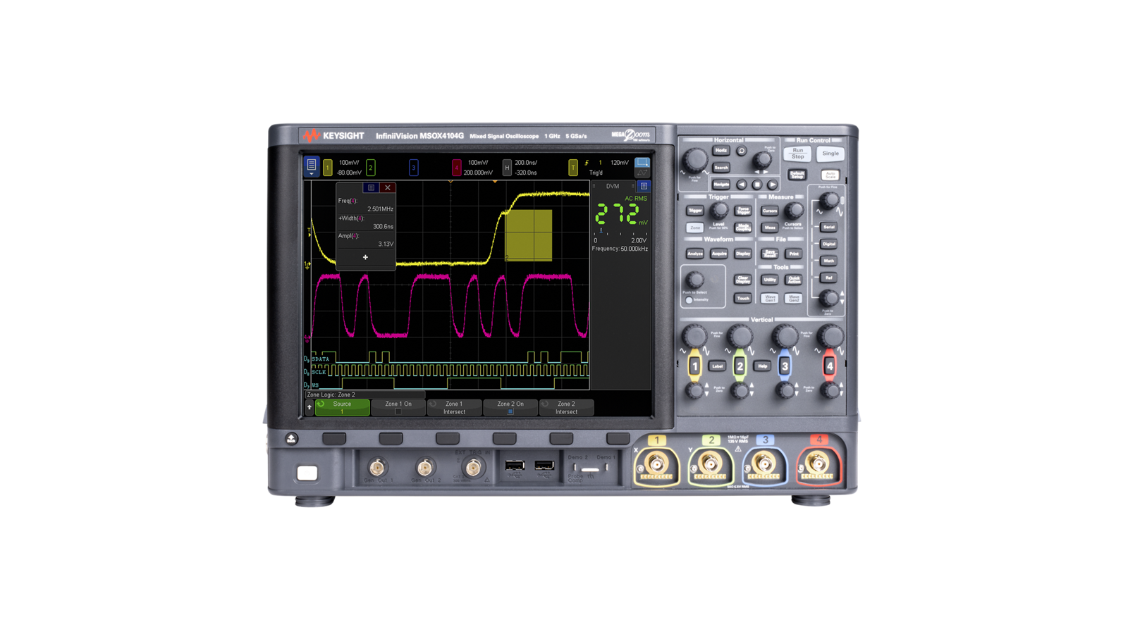
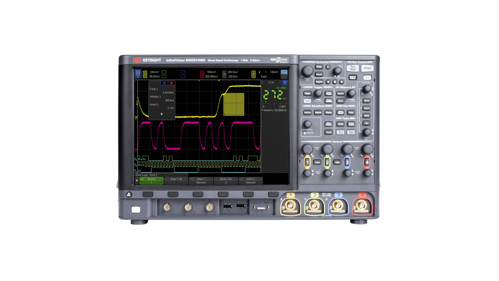
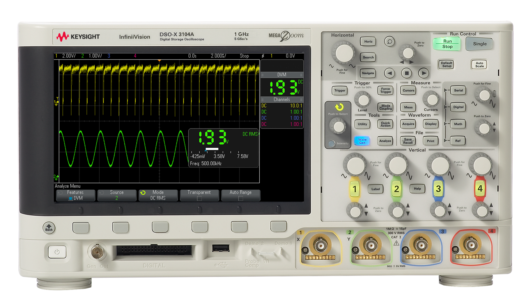
DSOX3104A 示波器 1GHz 详细指标
Benchtop Oscilloscopes
DSO and MSO
3000 X-Series oscilloscopes
3000 X-Series specification overview
3012A 3014A 3024A 3032A 3034A 3052A 3054A 3102A
3104A
Bandwidth1 (–3 dB) 100 MHz 200 MHz 350 MHz 500 MHz
1 GHz
Calculated rise time (10 to 90%) ≤ 3.5 ns ≤ 1.75 ns ≤ 1 ns ≤ 700 ps ≤
450 ps
Input channels DSOX 2 4 4 2 4 2 4 2
4
MSOX 2 + 16 4 + 16 4 + 16 2 + 16 4 + 16 2 + 16 4 + 16 2 + 16 4 +
16
Maximum sample rate 4 GSa/s half channel, 2 GSa/s all channel
5 GSa/s half ch
2.5 GSa/s all ch
Maximum memory depth 2 Mpts half channels, 1 Mpts all channels (4 Mpts half channels
2 Mpts all channels with
DSOX3MEMUP upgrade option)
Display size and type
8.5-inch WVGA display
Waveform update rate >
1 million waveforms per second
Number of active probes supported
In general, one for 2-channel models and two for 4-channel models. Contact Keysight for
Hardware bandwidth limits Approximately
20 MHz (selectable)
Input impedance Selectable: 1 MΩ ± 1% (14 pF), 50 Ω
± 1.5%
Input sensitivity range 100 MHz ~ 500 MHz models
1 mV/div to 5 V/div2 (1 MΩ and 50 Ω)
1 GHz models: 1 mV/div to 5 V/div2 (1 MΩ)
1 mV/div to 1 V/div (50 Ω)
Vertical resolution 8 bits (measurement resolution is
12 bits with averaging)
Maximum input voltage 135 Vrms
190 Vpk
Probing technology allows testing of higher voltages. For example, the included n2841A,
N2842A or N2843A
10:1 probe supports testing up to 300Vrms
Use this instrument only for measurements within its specified measurement category (not
条件:Channel-to-channel isolation > 100:1 from DC to maximum specified bandwidth of each model (measured with same
DC vertical gain accuracy 1 ± 2.0% full scale
2
DC vertical offset accuracy ± 0.1 div ± 2 mV
± 1% of offset setting
Offset range
± 2 V (1 mV/div to 200 mV/div)
± 50 V (>
200 mV/div to 5 V/div)
Digital input channels 16 digital (D0 to D15. pod 1: D7 ~ D0, Pod
2: D15 ~ D8)
Thresholds Threshold per pod
Threshold selections TTL (+1.4 V)
5V CMOS (+2.5 V), ECL (–1.3 V), user-defined (selectable by pod)
User-defined threshold range
± 8.0 V in 10 mV steps
Maximum input voltage
± 40 V peak CAT I
Threshold accuracy 1 ± (100 mV +
3% of threshold setting)
Maximum input dynamic range
± 10 V about threshold
Minimum voltage swing
500 mVpp
Input impedance 100 kΩ
± 2% at probe tip
Horizontal system analog channels 3012A 3014A 3024A 3032A 3034A 3052A 3054A 3102A
3104A
Time base range
5 ns/div to
50 s/div
2 ns/div to 50 s/div
1 ns/div to
50 s/div
500 ps/div to
50 s/div
Time base accuracy1 25 ppm
± 5 ppm per year (aging)
Pre-trigger Greater of 1 screen width or 250 μs
Channel-to-channel deskew range
± 100 ns
∆ Time accuracy (using cursors) ± (time base acc. x reading) ± (0.0016 x screen width)
± 100 ps
Modes Main, zoom, roll, XY
条件:XY On channels 1 and 2 only. Z Blanking on ext trigger input, 1.4 V threshold.
Bandwidth: Maximum bandwidth. Phase error at 1 MHz: <
0.5 degree.
Minimum detectable pulse width
5 ns
Channel-to-channel skew 2 ns (typical)
3 ns (maximum)
Acquisition system 3012A 3014A 3024A 3032A 3034A 3052A 3054A 3102A
3104A
Maximum analog channels sample rate 4 GSa/s half channel interleaved, 2 GSa/s all channel 5 GSa/s half channel interleaved
2.5
Maximum analog channels record length 2 Mpts half channel interleaved, 1 Mpts all channel (standard) 4 Mpts half channel interleaved
2 Mpts all channel (optional with DSOX3MEMUP
(-040))
Acquisition system 3012A 3014A 3024A 3032A 3034A 3052A 3054A 3102A
3104A
Maximum duration of time captured at highest sampling rate (all analog channels) 500 µs with 4M memory upgrade
400 µs with 4M
Maximum digital channels sample rate 1 GSa/s
1.25 GSa/s
Maximum digital channels record length 1 Mpts (standard - with digital channels only)
2 Mpts (optional with DSOX3MEMUP - with digital channels only)
Peak detect Capture glitches as narrow as
250 ps at all time base settings
Averaging Selectable from 2, 4, 8, 16
64, ... to 65,536
Real time boxcar averaging reduces random noise and effectively increases vertical
resolution 12 bits of resolution when ≥
10 μs/div at 4 GSa/s (5 GSa/s for 1 GHz models)
or ≥
20-μs/div at 2 GSa/s (2.5 GSa/s for 1 GHz models)
Segmented Segmented memory optimizes available memory for data streams that have long dead
times between activity. Maximum segments = 1000. Re-arm time =
1 μs
Trigger sources Analog channel (1~4), digital channel (D0~D15), line, external, WaveGen
(1 or mod) (FM/FSK)
Trigger modes Normal (triggered): Requires trigger event for scope to trigger
Auto: Triggers automatically in absence of trigger event
Single: Triggers only once on a trigger event, press [Single] again for scope to find
another trigger event, or press [Run] to trigger continuously in either Auto or Normal mode
AC: AC coupled trigger, cutoff frequency: < 10 Hz (internal); <
50 Hz (external)
HF Reject: High frequency reject, cutoff frequency ~
50 kHz
LF Reject: Low frequency reject, cutoff frequency ~
50 kHz
Noise Reject: Selectable OFF or ON, decreases sensitivity
2x
Trigger holdoff range
40 ns to 10.00 s
Internal 1 < 10 mV/div: greater of 1 div or 5 mV; ≥ 10 mV/div
0.6 div
External
200 mVpp from DC to 100 MHz
350 mVpp
100 MHz to 200 MHz
Any channel
± 6 div from center screen
Edge Trigger on a rising, falling, alternating or either edge of any source
Edge then edge (B trigger) Arm on a selected edge, wait a specified time, then trigger on a specified count of another
Pulse width Trigger on a pulse on a selected channel, whose time duration is less than a value, greater
条件:with a minimum time setting of 2~10 ns and maximum time setting of 10 s.
Minimum time setting: 2 ns (500 MHz, 1 GHz), 4 ns (350 MHz), 6 ns (200 MHz).
Minimum duration setting: 2 ns (500 MHz, 1 GHz), 4 ns (350 MHz)
6 ns (200 MHz)
10 ns (100 MHz)
Maximum duration setting
10 s
Runt Trigger on a position runt pulse that fails to exceed a high-level threshold. Trigger on a
negative runt pulse that fails to exceed a low-level threshold. Trigger on either polarity runt
pulse based on two threshold settings. Runt triggering can also be time-qualified (< or >)
10 ns (100 MHz)
Setup and hold Trigger and clock/data setup and/or hold time violation. Setup time can be set from –7 to
10 s. Hold time can be set from 0 s to 10 ns.
Rise/fall time Trigger on rise-time or fall-time edge speed violations (< or >) based on user-selectable
threshold. Select from (< or >) and time settings range between
Minimum: 1 ns (500 MHz, 1 GHz), 2 ns (350 MHz), 3 ns (200 MHz)
5 ns (100 MHz)
Nth edge burst Trigger on the Nth (1 to 65535) edge of a pulse burst. Specify idle time (10 ns to 10 s)
条件:minimum of 2 ns to qualify as a valid trigger condition.
Pattern Trigger when a specified pattern of high, low, and don’t care levels on any combination of
analog, digital, or trigger channels is [entered | exited]. Pattern must have stabilized for a
Minimum duration setting: 2 ns (500 MHz, 1 GHz), 4 ns (350 MHz)
6 ns (200 MHz)
10 ns (100 MHz)
Maximum duration setting
10 s
Or Trigger on any selected edge across multiple analog or digital channels
Video Trigger on all lines or individual lines, odd/even or all fields from composite video, or
broadcast standards (NTSC, PAL, SECAM, PAM-M)
条件:USB Trigger on start of packet, end of packet, reset complete, enter suspend, or exit suspend.
Enhanced Video (optional) Trigger on lines and fields of enhanced and HDTV standards (480p/60, 567p/50
720p/50
720p/60, 1080p/24, 1080p/25, 1080p/30, 1080p/50, 1080p/60, 1080i/50
1080i/60).
Support USB low-speed and full-speed
条件:I2C (optional) Trigger at a start/stop condition or user defined frame with address and/or data values.
Also trigger on missing acknowledge, address with no ack, restart, EEPROM read, and 10-
条件:SPI (optional) Trigger on SPI (Serial Peripheral Interface) data pattern during a specific framing period.
RS-232/422/485/UART (optional) Trigger on Rx or Tx start bit, stop bit or data content or parity error.
1. Denotes warranted specifications, all others are typical. Specifications are valid after a 30-minute warm -up
2. 1 mV/div and 2 mV/div are a magnification of 4 mV/div setting. For vertical accuracy calculations, use full scale
Supports positive and negative Chip Select framing as well as clock Idle framing and user-
specified number of bits per frame. Supports MOSI and MISO data.
period and
± 10 °C from firmware calibration temperature.
of 32 mV for 1 mV/div and 2 mV/div sensitivity setting.
I²S (optional) Trigger on
2’s complement data of audio left channel or right channel (=, ≠, <, >, > <, < >
increasing value, or decreasing value)
CAN (optional) Trigger on CAN (controller area network) version
2.0A and 2.0B signals. Trigger on the
start of frame (SOF) bit (standard). Remote frame ID (RTR), data frame ID (~RTR), remote
or data frame ID, data frame ID and data, error frame, all errors, acknowledge error and
LIN (optional) Trigger on LIN (Local Interconnect Network) sync break, sync frame ID, or frame ID and
FlexRay (optional) Trigger on frame ID, frame type (sync, start-up, null, normal), cycle-repetitive, cycle-base,
条件:Terminal Address, data, and errors (parity, sync, Manchester encoding).
range, error conditions (parity, word, gap, word or gap, all), all bits (eye), all 0 bits, all 1 bits.
MIL-STD 1553 (optional) Trigger on MIL-STD 1553 signals based on word type (Data or Command/Status), Remote
ARINC 429 (optional) Trigger and decode on ARINC429 data. Trigger on word start/stop, label, label + bits, label
Single cursor accuracy: ± [DC vertical gain accuracy + DC vertical offset accuracy +
0.25% full scale]
Dual cursor accuracy: ± [DC vertical gain accuracy + 0.5% full scale]
1
Units: Seconds(s), Hz (1/s), Phase (degrees), Ratio (%)
Measurements continuously updated with statistics. Cursors track last selected
measurement. Select up to four measurements from the list below:
• Voltage: Peak-to-peak, maximum, minimum, amplitude, top, base, overshoot,
pre-shoot, average- N cycles, average- full screen, DC RMS- N cycles, DC RMS-
full screen, AC RMS- N cycles, AC RMS- full screen (standard deviation), ratio
(RMS1/RMS2)
• Time: Period, frequency, counter, + width, - width, burst width, duty cycle, rise
时间, 下降时间, 延迟, 相位, X · 最小 Y, X · 最大 Y
• Count: Positive pulse count, negative pulse count, rising edge count, falling
Arithmetic f (g(t)) g(t): { add, subtract, multiply between any
2 channels} f(t): {FFT(g(t)), differentiate d/dt g(t), integrate ∫ g(t) dt, square root √g(t) }
Enabled between any combination of two channels
Arithmetic DSOX3ADVMath advanced waveform math option adds Ax + B, Square, Absolute,
Common Log, Natural Log, Exponential, Base
10 Exponential, LP Filter, HP Filter, Magnify
Measurement Trend, Chart Logic Bus (Timing or State)
FFT Up to 64 kpts resolution
Set FFT Window to: Hanning, Flat Top, Rectangular, Blackman-Harris
Resolution 800 (H) x
480 (V) pixel format (screen area)
Graticules 8 vertical divisions by
10 horizontal divisions with intensity controls
Maximum waveform update rate >
1,000,000 waveforms/sec
Persistence Off, infinite, variable persistence (100 ms to 60 s)
Intensity gradation
64 intensity levels
WaveGen – Built-in function/arbitrary waveform generator (specifications are typical)
WaveGen out 前面板-面板 BNC 连接器
Waveforms Sine, Square, Ramp, Pulse, DC, Noise, Sine Cardinal (Sinc), Exponential
Rise, Exponential Fall, Cardiac, Gaussian Pulse, and Arbitrary.
Carrier waveforms: sine, ramp, sine cardinal, exponential rise, exponential
Modulation source: internal (no external modulation capability)
• Modulation: sine, square, ramp
• Modulation frequency
1 Hz to 20 kHz
• Modulation: sine, square, ramp
• Modulation frequency
1 Hz to 20 kHz
• Minimum carrier frequency
10 Hz
• Deviation
1 Hz to carrier frequency or (2e12 / carrier frequency)
• Modulation
50% duty cycle square wave
• Hop frequency
2 x FSK rate to 10 MHz
Sine Frequency range
0.1 Hz to 20 MHz
Amplitude flatness
± 0.5 dB (relative to 1 kHz)
Harmonic distortion
–40 dBc
Spurious (non harmonics)
–40 dBc
Total harmonic distortion
1%
SNR (50 Ω load, 500 MHz BW): 40 dB (Vpp > = 0.1 V); 30 dB (Vpp <
0.1 V)
Square wave/pulse Frequency range
0.1 Hz to 10 MHz
Duty cycle resolution: Larger of 1% or 10 ns
Rise/fall time
18 ns (10 to 90%)
Pulse width resolution
10 ns or 5 digits, whichever is larger
Asymmetry (at 50% DC): ± 1%
± 5 ns
Ramp/triangle wave Frequency range
0.1 Hz to 200 kHz
Variable symmetry
0 to 100%
Noise Bandwidth
20 MHz typical
Sine cardinal (Sinc) Frequency range
0.1 Hz to 1.0 MHz
Exponential Rise/Fall Frequency range
0.1 Hz to 5.0 MHz
Cardiac Frequency range
0.1 Hz to 200.0 kHz
Gaussian Pulse Frequency range
0.1 Hz to 5.0 MHz
Arbitrary Waveform length
1 to 8k points
Amplitude resolution
10 bits (including sign bit) ***
Repetition rate
0.1 Hz to 12 MHz
• 130 ppm (frequency <
10 kHz)
• 50 ppm (frequency >
10 kHz)
• [50+frequency/200] ppm (frequency <
25 kHz)
• 50 ppm (frequency ≥
25 kHz)
Resolution
0.1 Hz or 4 digits, whichever is larger
• 20 mVpp to 5 Vpp into Hi-Z
2
• 10 mVpp to 2.5 Vpp into 50 ohms
2
Resolution
100 μV or 3 digits, whichever is higher
Accuracy: 2% (frequency =
1 kHz)
Resolution
100 μV or 3 digits, whichever is higher
Accuracy (waveform modes): ± 1.5% of offset setting ± 1% of amplitude
± 1 mV
Accuracy (DC mode): ± 1.5% of offset setting
± 3 mV
触发输出触发输出 available 开 Trig out BNC
Main Output Impedance
50 ohms typical
Resolution ACV/DCV: 3 digits Frequency
5.5 digits
Measuring rate
100 times/second
Autoranging Automatic adjustment of vertical amplification to maximize the dynamic range
Range meter Graphical display of most recent measurement, plus extrema over the previous
3 seconds
Standard ports One USB
2.0 hi-speed device port on rear panel. Supports USBTMC protocol
Two USB
2.0 hi-speed host ports, front and rear panel
Supports memory devices, printers and keyboards
条件:waveform generator sync pulse 1. Gaussian Pulse: 4 Vpp maximum into Hi -Z; 2 Vpp maximum into 50 ohms. 2. Sinc, Cardiac and Gaussian Pulse: ± 1.25 V into Hi -Z; ± 625 mV into 50 ohms. 3. Full resolution is not available at output due to internal attenuator stepping.
Optional ports GPIB, LAN (10/100Base-T), WVGA video out
Trigger out BNC connector on the rear panel. Supported modes: triggers, mask, and
Power line consumption
100 watts
Power voltage range 100 to 120 V, 50/60/400 Hz; 100 to 240 V
50/60 Hz
Environmental rating 5 to 50°C
4000 m max
Maximum Relative Humidity (non-condensing)
95%RH up to 40°C
From 40°C to 50°C, the maximum % Relative Humidity follows the line of
Electromagnetic compatibility Meets EMC Directive (2004/108/EC), meets or exceeds IEC
61326-1:2005/EN
61326-1:2006 Group
1 Class A requirement
IEC 61000-4-2/EN
61000-4-2
IEC 61000-4-3/EN
61000-4-3
IEC 61000-4-4/EN
61000-4-4
IEC 61000-4-5/EN
61000-4-5
IEC 61000-4-6/EN
61000-4-6
IEC 61000-4-11/EN
61000-4-11
Canada: ICES-001:2004
Australia/New Zealand: AS/NZS
Safety ANSI/UL Std. No. 61010-1:2012; CAN/CSA-C22.2 No.
61010-1-12
ANSI/UL Std. No. 61010-2-030:2012; CAN/CSA-C22.2 No.
61010-2-030-12
Vibration Meets IEC60068-2-6 and MIL-PRF-28800; class
3 random
Shock Meets IEC 60068-2-27 and MIL-PRF-28800; class 3 random; (operating
30 g
½ sine. 11 ms duration
3 shocks/axis along major axis, total of 18 shocks
Dimensions (W x H x D) 381 mm (15 in) x 204 mm (8 in) x
142 mm (5.6 in)
Weight Net: 3.9 kg (8.5 lbs.), shipping
4.1 kg (9.0 lbs.)
Reference waveform display
2 internal waveforms or USB thumb drive
Waveform storage Setup, .bmp, .png, .csv, ASCII, XY, reference waveforms .alb, .bin, lister,
Max USB flash drive size Supports flash drives
Set ups without USB flash drive
10 internal setups
Included standard with oscilloscope
Calibration Soft copy of Certificate of Calibration (CoC) with measurement results
downloadable from 2-year calibration interval
• N2841A Passive probe 150 MHz
10:1 attenuation
• N2842A Passive probe 300 MHz
10:1 attenuation
• N2843A Passive probe 500 MHz
10:1 attenuation
• N2756A
16 digital channel MSO cable
1 per channel included
100 MHz models
1 per channel included
200 MHz models
1 per channel included
350/500 MHz and 1 GHz models
1 per scope included on all MSO models and
DSOX3MSO (for
500 MHz models and below)
DSOX3PERFMSO (for
1 GHz Models)
Interface and built-in help language support
English, Japanese, simplified Chinese, traditional Chinese, Korean, German, French, Spanish, Russian,
Publication title Publication number
Power Software Package Data Sheet
5992-3925EN
Automotive Software Package Data Sheet
5992-3912EN
Embedded Software Package Data Sheet
5992-3924EN
Aero Software Package Data Sheet
5992-3910EN
Ultimate Bundle Software Package Data Sheet
5992-3918EN
DSOX3WAVEGEN Built-in
20 MHz function/AWG waveform generator upgrade (license only)
DSOX3MSO 16 digital timing channels upgrade for ≤
500 MHz BW models (license + MSO logic
probe delivered separately)
DSOX3PERFMSO
16 digital timing channels upgrade for 1 GHz BW models
(license + MSO logic probe delivered separately)
DSOX3MEMUP Acquisition memory upgrade from 2 to 4 Mpts (license only)
DSOX3BW52 Bandwidth upgrade from 350 to 500 MHz
2-ch models (license only)
DSOX3BW24 Bandwidth upgrade from 100 to 200 MHz
4-ch models (license only)
DSOX3BW54 Bandwidth upgrade from 350 to 500 MHz
4-ch models (license only)
D3000GENB Embedded Software Package: I2C, SPI, UART (RS232/422/485), and I2S serial
trigger and de-code, plus Mask Limit Testing, Enhanced Video Analysis, and Advanced
D3000AUTB Automotive Software Package: CAN, LIN, & FlexRay serial trigger and decode, plus
Mask Limit Testing and Advanced Waveform Math
D3000AERB Aero Software Package: MIL-STD 1553 and ARINC
429 serial trigger and decode, plus
Mask Limit Testing, Enhanced Video Analysis, and Advanced Waveform Math
D3000PWRB Power Software Package: Power quality, current harmonics, switching loss,
turn-on/off time, transient response & more, plus Mask List Testing and Advanced
条件:channel) will be sent with the upgrade. 2 For software packages, you will receive a paper or electronic .pdf Entitlement Certificate. For bandwidth upgrades only, you will receive a stick-on label document indicating upgraded bandwidth specification in addition to a paper Entitlement Certificate.
for a particular 2000 or 3000 X-Series oscilloscope model number and serial number unit.
purchased bandwidth upgrade or measurement application on the oscilloscope.
oscilloscope. Model number and serial number of the oscilloscope do not change.
D2000BDLA Ultimate Bundle Software Package: I2C, SPI, UART, I2S, CAN, LIN, FlexRay,
MIL-STD 1553, ARINC
429 serial trigger and decode, plus Mask Limit Testing
Enhanced Video Analysis, Advanced Waveform Math, and Power Analysis
Process description
1 Place order for a license-only upgrade product to a Keysight sales partner. If multiple bandwidth upgrade steps are needed, order all the corresponding upgrade products required to get from current bandwidth to desired bandwidth. In the case where the new bandwidth requires higher bandwidth passive probes, they
are included with the upgrade. For the DSOX3BW24, the N2842A 10:1
300 MHz passive probes (1 per
3 Use Entitlement Certificate containing instructions and certificate number needed to generate a license file
4 Receive the licensed file and installation instructions via email.
5 Copy license file (.lic extension) from email to a USB drive and follow instructions in email to install the
6 For bandwidth upgrades only, attach bandwidth upgraded stick-on label to front and rear panels of the
Return-to-Keysight Service Center Bandwidth Upgrades
条件:Process description 1 Place order for a return-to-Keysight Service Center bandwidth upgrade product to a Keysight sales partner.
Return-to-Keysight bandwidth upgrade models
3000 X-Series
DSOX3BW32 100 MHz to 350 MHz
2 ch, Service center
DSOX3BW34 200 MHz to 350 MHz
4 ch, Service center
DSOX3BW12 500 MHz to 1 GHz
2 ch, Service center
DSOX3BW14 500 MHz to 1 GHz
4 ch, Service center
Service Center installation, calibration, shipment costs are in addition to bandwidth upgrade product price. If
以上指标摘自厂家官方数据手册,完整定义、测试条件与保证值口径以手册为准。完整指标、测试条件与定义口径请见产品页「软件和手册 | 白皮书」栏目中的官方数据手册。
是德科技 | KEYSIGHT · onetest 仪器资源库



 客服








 粤公网安备44030902003758