是德科技 | KEYSIGHT
U1252B 万用表 详细指标
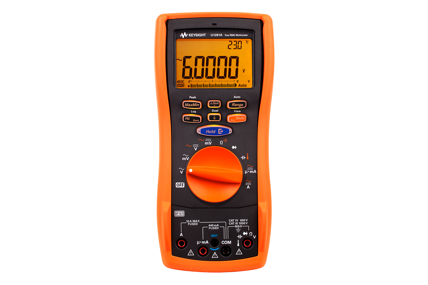
Make trustworthy measurements in harsh working environments
Function Range Resolution Accuracy ± (% of reading + no. of least significant digit)
Frequency 30 Hz ~ 45 Hz 45 Hz ~ 1 kHz 1 kHz ~ 5 kHz 5 kHz ~
30 kHz
True RMS Ac voltage 1, 2, 3 50.000 mV 0.001 mV
1.0+60
0.6+40 1.0+40 1.6+60 500.00 mV
0.01 mV
0.6+25
1.0+25 3.5+120 5.0000 V
0.0001 V
1000.0 V 0.1 V 0.6+40
1.0+40 N/A
条件:1. Input impedance: Refer to Table A on page 10.
2. ACV measurement is AC coupled; while ACmV and AC μA/mA/A measurement are DC coupled. All specifications are valid from
3. Crest factor ≤ 5 at half -scale, ≤ 3 at full -scale, and decrease reciprocally for overange as 3 * Full Scale / Input; except for
for overange as 1.5 * Full Scale / Input. For non -sinusoidal waveform, add 0.1 % of reading ±0.3 % of range.
4. These specifications are for typical performance.
5. Input current > 35 µARMS.
6. Input current < 3 ARMS.
7. Current can be measured from 2.5 A up to 10 A continuously. An additional 0.5% needs to be added to the specified accuracy if
meter to cool down for twice the measuring time used before application of low current measurement.
8. Additional error to be added for frequency > 15 kHz and signal input < 10 % of range: 3 counts of LSD per kH z.
Function Range Resolution Accuracy ± (% of reading + no. of least significant digit)
Frequency 20 Hz ~ 45 Hz 45 Hz ~ 1 kHz 1 kHz ~ 5 kHz 5 kHz ~ 15 kHz 15 kHz ~ 100 kHz
8
True RMS AC voltage 1, 2, 3 50.000 mV 0.001 mV
1.5+60
0.75+40
3.5+120
0.75+40
5.0000 V 0.0001 V 0.6+25 1.5+40 50.000 V 0.001 V 0.4+25 500.00 V
0.01 V N/A N/A
1000.0 V 0.1 V 0.4+40
0.4+40 N/A N/A
5% to 100% of range.
1000 mV and 1000 V ranges, where this ranges have crest factor ≤ 3 at half -scale, ≤
1.5 at full scale, and decrease reciprocally
the signal measured is in the range of 10 A ~ 20 A for 30 seconds maximum. After measuring a current of >
10 A, leave the
Function Range Resolution Accuracy ± (% of reading + no. of least significant digit)
Frequency 30 Hz ~ 45 Hz 45 Hz ~ 2 kHz 2 kHz ~ 20 kHz
4
500.00 µA 5 0.01 µA
1.5+50
0.8+20
5.0000 A 0.0001 A 2.0+40 6 10.000 A 7 0.001 A 3+60, <
3 A/5 kHz
Function Range Resolution Accuracy ± (% of reading + no. of least significant digit)
Frequency 20 Hz ~ 45 Hz 45 Hz ~ 1 Khz 1 Khz ~ 20 Khz 1 20 Khz~100 Khz
2
True RMS AC current 3, 4 500.00 µA 5 0.01 µA
1.0+20
0.7+20
0.75+20 5.0+80 5000.0 µA
0.1 µA
5.0000 A 0.0001 A 1.5+20 6 3+60, < 3 A/5 kHz N/A 10.000 A
0.001 A
U1252B/U1253B AC 电流规格 · U1252B/U1253B AC+DC 电压规格
条件:1. These specifications are for typical performance.
2. Additional error to be added for frequency > 15 kHz and signal input < 10 % of range: 3 counts of LSD per kHz.
3. ACV measurement is AC coupled; while ACmV and AC μA/mA/A measurement are DC coupled. All specifications are valid from
4. Crest factor ≤ 5 at half -scale, ≤ 3 at full -scale, and decrease reciprocally for overange as 3 * Full Scale / Input; except for
for overange as 1.5 * Full Scale / Input. For non -sinusoidal waveform, add 0.1 % of reading ±0.3 % of range.
5. Input current > 35 µARMS.
6. Input current < 3 ARMS.
7. Current can be measured from 2.5 A up to 10 A continuously. An additional 0.5% needs to be added to the specified accuracy if
meter to cool down for twice the measuring time used before application of low current measurement.
8. Input impedance: Refer to Table A on page 10.
9. The maximum displayable counts is 51000, except for 1000.0 mV, 1000.0 V and 10 A ranges, where the maximum displayable
Function Range Resolution Accuracy ± (% of reading + no. of least significant digit)
Frequency 30 Hz ~ 45 Hz 45 Hz ~ 1 kHz 1 kHz ~ 5 kHz 5 kHz ~ 15 kHz 15 kHz ~ 100 kHz
2
True RMS AC voltage 3, 8, 9 50.000 mv 0.001 mv 1.5+80 0.4+60 0.7+60 0.8+60 3.5+220 500.00 mV
0.01 mV
5.0000 V 0.0001 V 0.6+30 1.5+45 50.000 V 0.001 V 0.4+30 500.00 V
0.01 V N/A N/A
1000.00 V 0.1 V 0.4+45
0.4+45 N/A N/A
5% to 100% of range.
1000 mV and 1000 V ranges, where this ranges have crest factor ≤ 3 at half -scale, ≤
1.5 at full scale, and decrease reciprocally
the signal measured is in the range of 10 A ~ 20 A for 30 seconds maximum. After measuring a current of >
10 A, leave the
counts is 15000. “0.L” will be shown for any resultant AC+DC voltage/current that exceeds the maximum displayable counts in
manual range. Subject to operate within the product specifications.
FLYER · U1252B/U1253B AC+DC 电流规格
条件:1. These specifications are for typical performance.
2. The maximum displayable counts is 51000, except for 1000.0 mV, 1000.0 V and 10 A ranges, where the maximum displayable
3. Input current > 35 µARMS.
4. Input current < 3 ARMS.
5. Current can be measured from 2.5 A up to 10 A continuously. An additional 0.5% needs to be added to the specified accuracy if
meter to cool down for twice the measuring time used before application of low current measurement.
6. The accuracy does not include the tolerance of the thermocouple probe. The thermal sensor plugged into the meter should be
placed in the operating environment for at least an hour. 7. Use the Null function to reduce the thermal effect. Before using the Null function, set the meter to no ambient compensation (0C) mode and keep the thermocouple probe as close to the meter as possible, avoiding contact with any surface that has a different temperature from the ambient temperature.
8. When measuring temperature with respect to any temperature calibrator, try to set both the calibrator and the meter with an
differences in ambient compensation between the calibrator and the meter.
U1251B/U1252B temperature specifications 6, 7
8
U1253B temperature specifications 6, 7
8
counts is 15000. “0.L” will be shown for any resultant AC+DC voltage/current that exceeds the maximum displayable counts in
manual range. Subject to operate within the product specifications.
the signal measured is in the range of 10 A ~ 20 A for 30 seconds maximum. After measuring a current of >
10 A, leave the
external reference (without internal ambient compensation). If both the calibrator and the meter are set with internal refere nce
(with internal ambient compensation), deviation may show between the readings of the calibrator and the meter, due to
Function Range Resolution Accuracy ± (% of reading + no. of least significant digit)
Frequency 30 Hz ~ 45 Hz 45 Hz ~ 1 kHz 1 1 kHz ~ 20 kHz
1
True RMS AC current 2 500.00 µA 3 0.01 µA 1.1+25 0.8+25 0.8+25 5000.0 µA 0.1 µA 50.000 mA 0.001 mA 1.2+25 0.9+25 0.9+25 440.00 mA
0.01 mA
5.0000 A 0.0001 A 1.8+30 4 0.9+30 3.3+70, < 3 A/5 kHz 10.000 A 5 0.001 A
0.9+25
Thermocouple 类型范围分辨率精度 ºC ºF ºC ºF
K –200 ~ 1372 ºC –328 ~ 2502 ºF 0.1 ºC/0.1 ºF 0.3% + 3 ºC 0.3% +
6 ºF
J (for U1252A/U1252B) –210 ~ 1200 ºC –346 ~ 2192 ºF 0.1 ºC/0.1 ºF 0.3% + 3 ºC 0.3% +
6 ºF
Thermocouple 类型范围分辨率精度 ºC ºF ºC ºF
K –200 ~ –40 °C –104 ~ –40 °F 0.1 ºC/0.1 ºF 1% + 3 °C 1% +
5.4 °F
–40 ~1372 °C –40 ~ 2502 °F 0.1 °C /0.1 °F 1% + 1 °C 1% +
1.8 °F
J –210 ~ –40 °C –346 ~ –40 °F 0.1 °C /0.1 °F 1% + 3 °C 1% +
5.4 °F
–40 ~ 1200 °C –40 ~ 2192 °F 0.1 °C /0.1 °F 1% + 1 °C 1% +
1.8 °F
条件:measurement 1. The input signal is lower than the product of 20000000 V x Hz (product voltage and frequency); overload protection: 1000 V. 2. Maximum input for specified accuracy = 10 x range or 1000 V .
U1251B frequency sensitivity during voltage
Range Resolution Accuracy Measuring rate at full scale Maximum display
10.000 nF 0.001 nF 1% + 8
4 times/sec.
11000 counts
1000.0 µF 0.1 µF
1 time/sec.
10.000 mF 0.001 mF
0.1 times/sec.
100.00 mF 0.01 mF 3% + 10
0.01 times/sec
Range Resolution Accuracy Min. input frequency
1
99.999 Hz 0.001 Hz 0.02%+3
0.02%+3
1 Hz
999.99 Hz 0.01 Hz 0.02%+3, < 600 kHz 0.02%+3, <
600 kHz
Input range
2 Minimum sensitivity (R.M.S. Sine Wave) Trigger level for DC coupling
(Maximum input for specified accuracy = 10 x Range or 1000 V) 20 Hz - 100 kHz ˃ 100 kHz ~ 200 kHz < 100 kHz ˃ 100 kHz ~ 200 kHz 50.000 mV 10 mV 15 mV 10 mV 15 mV 500.00 mV 25 mV 35 mV 60 mV
70 mV
1000.0 mV 40 mV 50 mV 100 mV
150 mV
5.0000 V 0.25 V 0.5 V 0.5 V / 1.25 V (< 100 Hz)
0.6 V
50.000 V 2.5 V 5 V 5 V
6 V
500.00 V 25 V N/A
50 V N/A
1000.0 V 50 V N/A
300 V N/A
U1252B/U1253B frequency sensitivity during voltage
条件:1. Maximum input for specified accuracy = 10 x range or 1000 V.
2. The positive or negative pulse width must be greater than 10 µs, and the duty cycle range should be considered. The pulse
Duty cycle and pulse width
2
Input range
1 Minimum sensitivity (R.M.S. Sine Wave) Trigger level for DC coupling
(Maximum input for specified accuracy = 10 x Range or 1000 V) 20 Hz - 100 kHz ˃ 200 kHz ~ 500 kHz < 100 kHz ˃ 100 kHz ~ 500 kHz 50.000 mV 10 mV 25 mV 10 mV 25 mV 500.00 mV 70 mV 150 mV 70 mV
150 mV
1000.0 mV 120 mV 300 mV 120 mV
300 mV
5.0000 V 0.3 V 1.2 V 0.6 V
1.5 V
500.00 V 30 V < 100 kHz N/A
60 V N/A
1000.0 V 50 V < 100 kHz N/A
120 V N/A
Input range Minimum sensitivity (RMS sine wave) 20 Hz ~
20 Khz
信号 width 精度 · DC mV/电压/电流
Single event > 1 ms 2% +
400 for all ranges
Repetitive > 250 µs 2% +
1000 for all ranges
Duty cycle DC Coupling 0.01% ~ 99.99% 0.3% per kHz +
0.3%
Pulse width 500 ms 0.01 ms 0.2% +
3
条件:Display rate 1. All frequency counters are susceptible to errors. Shielding inputs from external noise pickup is critical to minimize measu rement errors. For non -square wave signals, add 5 counts. 2. Output impedance: 3.5 kΩ maximum.
3. The positive or negative pulse width must be greater than 50 µs for adjustment of the duty cycle or pulse width under diffe rent
frequencies. Otherwise, the accuracy and range will be different from the specifications defined.
4. For signal frequencies greater than 1 kHz, an addition of 0.1% per kHz is added to the accuracy.
U1252B/U1253B square wave output
Division Range Resolution Accuracy ± (% of reading + no. of least significant digit) Sensitivity Min. input frequency
(secondary display “-1-“)
99.999 Hz 0.001 Hz 0.02% + 3 1 0.02% + 3 1
300 mV R.M.S.
0.5 Hz
< 30 Vpp
< 985 kHz
200 mV R.M.S. 9.9999 kHz
0.0001 kHz
600 mV R.M.S. 9.9999 MHz 0.0001 MHz 0.002% +
5
< 1 MHz
(secondary display “-100-“)
9.9999 MHz 0.0001 MHz 0.002% +
5
< 20 MHz
< 20 MHz
600 mV R.M.S. 1 MHz 99.999 MHz 0.001 MHz
1500 mV R.M.S.
Output
2 Range Resolution Accuracy
Frequency 0.5, 1, 2, 5, 6 6, 10, 15, 20, 25, 30, 40, 50, 60, 75, 80, 100, 120, 150, 200, 240, 300, 400, 480, 600, 800, 1200, 1600, 2400
48000 Hz
Duty cycle 3 0.39% ~ 99.60% 0.390625% 0.4% of full scale
4
Pulse width 4 1/frequency Range/256
0.2 ms + range/256
Amplitude Fixed 0 ~ +2.8 V 0.1 V
0.2 V
Capacitance 4 (<
100 µF)
Duty cycle/pulse width
0.5 (>10 Hz)
条件:Table A 1. For data logging to PC, maximum number of data points is dependent on available hard disk space.
Logging type Maximum data points
1
适用型号 U1251B U1252B U1253B
dB Base Reference Default reference 1 mΩ (dBm) 1-9999 Ω 50 Ω 1 V (dBV) 1 V
1 V
条件:5 V to 1000 V 10 MΩ (nominal) in parallel with 10 MΩ, < 100 pF
AC voltage 50 mV to 1000 mV 10 MΩ in parallel with < 100 pF 10 MΩ in parallel with < 100 pF
5 V to 1000 V
AC + DC voltage 50 mV to 1000 mV N/A
10 MΩ
条件:Both the primary and secondary displays offer a maximum resolution of 50,000 counts.
Both primary and secondary displays are
5-digit on the LCD display.
Power consumption 105 mVA/420 mVA (with backlight) maximum (U1251B) 165 mVA/480 mVA (with backlight) maximum (U1252B)
420 mVA maximum (U1253B)
Battery type 9 V alkaline battery (ANSI/NEDA 1604A or IEC 6LR61) 9 V carbon-zinc battery (ANSI/NEDA 1604D or IEC6F22)
7.2 V or 8.4 V Ni-MH rechargeable battery
• Full accuracy at –20 °C to 55 °C; and to 80% RH for temperatures up to 35 °C, decreasing linearly to
50% RH at 55 °C
• 0 to 2000 m altitude per IEC 61010-1 2nd Edition CAT III, 1000 V/CAT IV
600 V
–40 °C to 70 °C with battery removed
CAT III 1000 V / CAT IV
600 V
条件:electromagnetic phenomena, some recoverable degradation of performance may occur.
Refer to Declaration of Conformity for the latest revisions of regulatory compliance at
Note: If used in close proximity to an RF transmitter or when subjected to continuously present
Common Mode Rejection Ratio (CMRR)
U1251B/U1252B: > 90 dB at DC, 50/60 Hz
±0.1% (1 kW unbalanced)
U1253B: > 100 dB at DC, 50/60 Hz
±0.1% (1 kW unbalanced)
Normal Mode Rejection Ratio (NMRR)
U1251B/U1252B: > 60 dB at DC, 50/60 Hz
±0.1%
U1253B: > 90 dB at DC, 50/60 Hz
±0.1%
Temperature coefficient 0.15 * (specified accuracy)/°C (from
-20 °C to 18 °C or 28 °C to 55 °C)
Dimensions (HxWxD) 203.5 mm x 94.4 mm x
59.0 mm
U1251B
504±5 g with battery
U1252B/U1253B
527±5 g with battery
U1161A extended test
条件:Includes two test leads (red and black), two test probes, medium-sized alligator clips and 4-mm banana plugs.
• Test leads: CAT III
1000 V, CAT IV
• Test probes: CAT lll 1000 V, CAT lV
600
V, 15 A
• Medium sized alligator clips: CAT III 1000 V, CAT IV 600 V
15 A
• 4-mm banana plugs: CAT II 600 V
10 A
U1162A alligator clips
• One pair of insulated alligator clips (red and black). Recommended for use with
• Rated CAT III 1000 V, CAT IV 600 V
15
A
U1163A SMT grabbers
• One pair of fine-tip test probes (red and black). Recommended for use with
U1168A standard test lead kit
Includes two test leads (red and black)
19-mm and 4-mm test probes, alligator clips, fine-
tip test probes, SMT grabbers and mini grabber (black)
• Test leads: CAT III
1000 V, CAT IV
• Test probes (19mm tip): CAT II
1000 V
15 A
• Test probes (4-mm tip): CAT III
1000 V
recommended for CAT IV environment)
• Alligator clips: CAT III
1000V, CAT IV
• Fine-tip test probes: CAT II 300 V
3 A
• SMT grabber: CAT II 300 V
3 A
• Mini grabber: CAT II 300 V
3 A
U1583B AC current clamp
• Dual range
40 A and 400 A
U1180A thermocouple adapter +
Includes thermocouple adapter, thermocouple bead J-type and thermocouple
• T/C bead J-type
–20 °C to 200 °C
• T/C bead K-type
–20 °C to 200 °C
U1183A air temperature probe
• Type-K T/C for use in air and non- caustic gas
• Measurement range
–50 ºC to 800 ºC
• Includes adapter U1184A for connection
U1181A immersion temperature
• Type-K T/C for use in oil and other liquids
• Measurement range
–50 °C to 700 ºC
• Includes adapter U1184A for connection
U1182A industrial surface
• Type-K T/C for use on still surfaces
• Measurement range
–50 ºC to 400 ºC
• Includes adapter U1184A for connection to DMM
U1184A temperature probe
• Mini-connector-to-banana-plug adapter for use with DMM
U1185A J-type thermocouple and
• T/C bead J-type
–20 °C to 200 °C
U1186A K-type thermocouple and
• T/C bead J-type
–20 °C to 200 °C
Keysight enables innovators to push the boundaries of engineering by quickly solving
design, emulation, and test challenges to create the best product experiences. Start your
This information is subject to change without notice. © Keysight Technologies, 201 1 – 202
4
Published in USA, October 1, 202 4, 5 989
-5509 EN
U1172A transit case
• Aluminum-clad, black panel construction
• Dimension: 18” (H) x 13” (W) x
6“ (D)
U1174A soft carrying case
The convenient way to carry your DMM and essential accessories.
• Dimension: 9” (H) x 5” (W) x
3” (D)
U1171A magnetic hanging kit
For fastening of DMM to a steel surface so both hands are free.
U1170A AC adaptor
以上指标摘自厂家官方数据手册,完整定义、测试条件与保证值口径以手册为准。完整指标、测试条件与定义口径请见产品页「软件和手册 | 白皮书」栏目中的官方数据手册。
是德科技 | KEYSIGHT · onetest 仪器资源库



 客服








 粤公网安备44030902003758