 个人中心
个人中心分析仪调谐时间(典型)1 ms
频率范围:250 kHz 至10/20GHz
最大输出功率15 dBm
模块宽度:3
相位噪声:-130dBc@1GHz@10kHz
ONETEST 欢迎您


分析仪调谐时间(典型)1 ms
频率范围:250 kHz 至10/20GHz
最大输出功率15 dBm
模块宽度:3
相位噪声:-130dBc@1GHz@10kHz
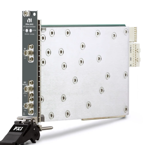
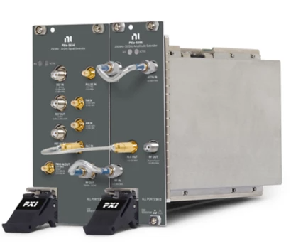
PXIe,250 kHz~20 GHz,PXI RF模拟信号发生器
PXIe-5654兼具有出色的相位噪声和频率调谐时间。这些特性使其非常适用于拦截器测试/接收器减敏、高性能互调失真测量和各种电子战应用。PXIe-5654专为满足RFIC特性分析、卫星测试和雷达应用等高难度要求而设计。某些PXIe-5654型号带有PXIe-5696扩幅器模块。PXIe-5696支持250 kHz至20 GHz的频率范围以及高达27 dBm的扩展幅度范围。
产品编号: 783127-02 | 783127-01 | 784777-02 | 784777-01 | 784776-02 | 784776-01 | 783126-02 | 783126-01
Range 250 kHz to 20 GHz Resolution 0.001 Hz Accuracy Refer to the Reference Clock section.Frequency
Frequency Settling Time
Frequency settling time[1],[2],[3] (nominal)Standard[4],[5]1 msFast tuning[4],[5],[6]100 µs
Initial accuracy | ±0.1 ppm, maximum |
Temperature (15 °C to 35 °C) | ±0.2 ppm, maximum |
Aging (per day, after 30 days) | ±0.01 ppm, maximum |
Aging (over 10 years) | ±1.25 ppm, maximum |
Connector name | REF OUT |
Frequency | 10 MHz |
Amplitude | +5 dBm ± 2 dB |
Coupling | AC |
Output impedance | 50 Ω |
Connector name | REF OUT 2 |
Frequency | 100 MHz |
Amplitude | +5 dBm ± 2 dB |
Coupling | AC |
Output impedance | 50 Ω |
Connector name | REF IN |
Frequency | 1 MHz to 20 MHz in 1 MHz steps |
Amplitude | -10 dBm to +10 dBm |
Input impedance | 50 Ω |
Lock time to external reference | < 2 s |
| Frequency (GHz) | Phase Noise (dBc/Hz) | |||||
|---|---|---|---|---|---|---|
| 100 Hz | 1 kHz | 10 kHz | 100 kHz | 1 MHz | 10 MHz | |
| 0.5 | -111, typical | -131, typical[7] | -137, typical | -139, typical | -140, typical | -147, typical |
| -107, max | -127, max[7] | -135, max | -137, max | -138, max | — | |
| 1 | -105, typical | -125, typical | -133, typical | -133, typical | -134, typical | -141, typical |
| -101, max | -121, max | -130, max | -131, max | -132, max | — | |
| 5 | -91, typical | -111, typical | -124, typical | -125, typical | -127, typical | -136, typical |
| -87, max | -109, max | -120, max | -122, max | -125, max | — | |
| 10 | -85, typical | -105, typical | -117, typical | -119, typical | -121, typical | -136, typical |
| -81, max | -103, max | -114, max | -117, max | -119, max | — | |
| 20 | -79, typical | -99, typical | -111, typical | -113, typical | -115, typical | -130, typical |
| -75, max | -97, max | -108, max | -111, max | -113, max | — | |

| Frequency | Harmonics (dBc) | |
|---|---|---|
| PXIe-5654 [8] | PXIe-5654 with PXIe-5696[9] | |
| 250 kHz to < 25 MHz | ≤ -18 | ≤ -20 |
| 25 MHz to < 250 MHz | ≤ -20 | ≤ -20 |
| 250 MHz to < 1 GHz | ≤ -25 | ≤ -25 |
| 1 GHz to < 2 GHz | ≤ -30 | ≤ -30 |
| 2 GHz to < 12 GHz | ≤ -40 [10] | ≤ -55 |
| 12 GHz to 20 GHz | ≤ -40 | ≤ -50 |

| Frequency | Subharmonics (dBc) | |
|---|---|---|
| PXIe-5654 [8] | PXIe-5654 with PXIe-5696[9] | |
| 250 kHz to < 10 GHz | -65 | -65 |
| 10 GHz to < 12 GHz | -60 | -60 |
| 12 GHz to 20 GHz | -50 | -45 |
| Frequency | Nonharmonic Spurs (dBc) | |
|---|---|---|
| PXIe-5654 [8] | PXIe-5654 with PXIe-5696[9] | |
| 250 kHz to < 8 GHz | -65 | -65 |
| 8 GHz to < 10 GHz | -60 | -60 |
| 10 GHz to 20 GHz | -60 | -55 |


| Frequency | PXIe-5654 | PXIe-5654 with PXIe-5696 | ||
|---|---|---|---|---|
| Specification | Typical | Specification[11] | Typical | |
| 250 kHz to ≤ 250 MHz | +10 | +12 | +10 | +13 |
| 250 MHz to ≤ 1 GHz | +13 | +14 | +20 | +23 |
| 1 GHz to ≤ 3 GHz | +13 | +14 | +24 | +27 |
| 3 GHz to ≤ 6 GHz | +13 | +15 | +23 | +26 |
| 6 GHz to ≤ 8 GHz | +13 | +15 | +20 | +25 |
| 8 GHz to ≤ 12 GHz | +13 | +14 | +20 | +22 |
| 12 GHz to ≤ 15 GHz | +13 | +15 | +20 | +21 |
| 15 GHz to ≤ 18 GHz | +13 | +15 | +18 | +21 |
| 18 GHz to ≤ 20 GHz | +12 | +14 | +18 | +20 |
| Frequency | PXIe-5654 | PXIe-5654 with PXIe-5696 |
|---|---|---|
| 250 kHz to < 250 MHz | -10 | -110 |
| 250 MHz to < 2 GHz | -7 | -110 |
| 2 GHz to < 18 GHz | -7 | -110 |
| 18 GHz to 20 GHz | -7 | -110 |
Resolution | 0.01 dB |

±2 dB, typical[14] |
| Center Frequency | > +13 dBm to Maximum Leveled Power | -10 dBm to +13 dBm[16] | -40 dBm to < -10 dBm | -80 dBm to < -40 dBm | -100 dBm to < -80 dBm | -110 dBm to < -100 dBm |
|---|---|---|---|---|---|---|
| ≤ 250 MHz | — | ±0.35, typical | ±0.60, typical | ±0.70, typical | ±2.0, typical | ±2.5, typical |
| — | ±0.80, max | ±1.20, max | ±1.50, max[17] | — | — | |
| 250 MHz to < 8 GHz | ±0.60, typical | ±0.35, typical | ±0.60, typical | ±0.70, typical | ±2.0, typical | ±2.5, typical |
| ±1.20, max | ±0.80, max | ±1.20, max | ±1.50, max | — | — | |
| 8 GHz to 20 GHz | ±0.60, typical | ±0.35, typical | ±0.60, typical | ±0.70, typical | ±2.0, typical | ±2.5, typical |
| ±1.30, max | ±0.80, max | ±1.20, max | ±1.50, max | — | — |


| Final Frequency | PXIe-5654 [18] , [19] | PXIe-5654 with PXIe-5696 (Open-Loop Mode)[19],[20] | PXIe-5654 with PXIe-5696 (Closed-Loop Mode)[21],[22] | |||
|---|---|---|---|---|---|---|
| 1.5 dB Settling Time | 2 dB Settling Time | 1.5 dB Settling Time | 2 dB Settling Time | 0.2 dB Settling Time | 0.5 dB Settling Time | |
| < 250 MHz | 4 ms | 3.5 ms | 4 ms | 3.5 ms | 4 ms | 3 ms |
| > 250 MHz | 500 µs | 300 µs | 500 µs | 300 µs | 4 ms | 3 ms |
0.2 dB amplitude settling time[23] | 25 ms, typical |

Broadband noise floor[25] | < -145 dBc/Hz, typical at > 20 MHz offset |
| Amplification Path[26] | Frequency Range | VSWR |
|---|---|---|
| Low harmonic path | 250 kHz to 8 GHz | < 1.6 : 1 |
| 8 GHz to 20 GHz | < 2.0 : 1 | |
| High power path | 1 GHz to 20 GHz | < 2.0 : 1 |
Output impedance | 50 Ω |
Supported modulation types[27] | Amplitude modulation (AM), frequency modulation (FM), phase modulation (PM), and pulse modulation |
Connector name | AM IN |
Modulation rate | DC to 100 kHz |
Input level | ±1 V, nominal |
AM range[28] | ±10 dB, nominal |
Maximum input level | +2 V |
Minimum input level | -2 V |
Input impedance | 50 Ω, nominal |
Connector name | FM IN |
| FM operating modes100 Hz to 1 kHz modulating signal rateNarrowband1 kHz to 10 kHz modulating signal rateNarrowband10 kHz to 100 kHz modulating signal rateNarrowband> 100 kHz modulating signal rateWideband | |
| PM operating modesDC modulating signal rateLow phase noiseDC to 100 kHz modulating signal rateHigh deviation | |

| FM and PM division constants[29]10,400 MHz to 20,800 MHzN = 15,200 MHz to 10,400 MHzN = 22,600 MHz to 5,200 MHzN = 41,300 MHz to 2,600 MHzN = 8650 MHz to 1,300 MHzN = 16325 MHz to 650 MHzN = 32250 MHz to 325 MHzN = 64 |
Connector name | PULSE IN |
Repetition frequency | DC to 10 MHz |
| Input levelRF onTTL highRF offTTL lowMaximum+5.5 VMinimum-0.5 V | |
Input impedance | > 100 kΩ |
Carrier on/off ratio (250 MHz to 20 GHz)[31] | 80 dB |

Minimum pulse width (250 MHz to 20 GHz) | 50 ns, typical |
Rise/fall time (250 MHz to 20 GHz) | 15 ns |
Maximum pulse width compression[32] (250 MHz to 20 GHz) | 15 ns, nominal |
Delay time (250 MHz to 20 GHz) | < 35 ns, nominal |
Pulse overshoot (250 MHz to 20 GHz) | < 10% |
| Voltage (VDC) | Maximum Current (A) | Typical Current (A) |
|---|---|---|
| +3.3 | 2.5 | 1.9 |
| +12 | 3 | 2.4 |
| Voltage (VDC) | Maximum Current (A) | Typical Current (A) |
|---|---|---|
| +3.3 | 3 | 2.2 |
| +12 | 2.8 | 1.6 |
Interval | 2 years |
| PXIe-5654 RF signal generatorSize3U, three slot, PXI Express module 6.1 cm x 13.0 cm x 21.4 cm(2.4 in. x 5.1 in. x 8.4 in.)Weight1,328 g (46.8 oz) | |
| PXIe-5696 amplitude extenderSize3U, two slot, PXI Express module 4.1 cm x 13.0 cm x 21.4 cm(1.6 in. x 5.1 in. x 8.4 in.)Weight894 g (31.5 oz) |
Maximum altitude | 2,000 m (800 mbar) (at 25 °C ambient temperature) |
Pollution Degree | 2 |
Indoor use only.
Ambient temperature range | 0 °C to 55 °C |
Relative humidity range | 10% to 90%, noncondensing |
Ambient temperature range | -40 °C to 71 °C |
Relative humidity range | 5% to 95%, noncondensing |
Operating shock | 30 g peak, half-sine, 11 ms pulse |
| Random vibrationOperating5 Hz to 500 Hz, 0.3 g RMSNonoperating5 Hz to 500 Hz, 2.4 g RMS | |
This product is designed to meet the requirements of the following electrical equipment safety standards for measurement, control, and laboratory use:
IEC 61010-1, EN 61010-1
UL 61010-1, CSA C22.2 No. 61010-1
0条提问
X
提问
X
回答
发表口碑
© 2026 Onetest仪器资源库 All Rights Reserved 粤ICP备17028186号-2
 粤公网安备44030902003758