是德科技 | KEYSIGHT
PNA-X系列N5245B 10MHz至50GHz 网络分析仪 详细指标
Benchtop Vector Network Analyzers
THE MATERIAL CONTAINED IN THIS DOCUMENT IS PROVIDED "AS IS," AND IS SUBJECT TO
BEING CHANGED, WITHOUT NOTICE, IN FUTURE EDITIONS. FURTHER, TO THE MAXIMUM
EXTENT PERMITTED BY APPLICABLE LAW, KEYSIGHT DISCLAIMS ALL WARRANTIES, EITHER
EXPRESS OR IMPLIED WITH REGARD TO THIS MANUAL AND ANY INFORMATION CONTAINED
HEREIN, INCLUDING BUT NOT LIMITED TO THE IMPLIED WARRANTIES OF MERCHANTABILITY
AND FITNESS FOR A PARTICULAR PURPOSE. KEYSIGHT SHALL NOT BE LIABLE FOR ERRORS
OR FOR INCIDENTAL OR CONSEQUENTIAL DAMAGES IN CONNECTION WITH THE
FURNISHING, USE, OR PERFORMANCE OF THIS DOCUMENT OR ANY INFORMATION
CONTAINED HEREIN. SHOULD KEYSIGHT AND THE USER HAVE A SEPARATE WRITTEN
AGREEMENT WITH WARRANTY TERMS COVERING THE MATERIAL IN THIS DOCUMENT THAT
CONFLICT WITH THESE TERMS, THE WARRANTY TERMS IN THE SEPARATE AGREEMENT WILL
条件:Limited Rights as defined in FAR 27.401 or DFAR 227.7103-5 (c), as applicable in any technical data.
U.S. Government Rights. The Software is “commercial computer software,” as defined by Federal
Acquisition Regulation (“FAR”) 2.101. Pursuant to FAR
12.212 and 27.405-3 and Department of
Defense FAR Supplement (“DFARS”)
227.7202, the U.S. government acquires commercial computer
software under the same terms by which the software is customarily provided to the public. Accordingly,
Keysight provides the Software to U.S. government customers under its standard commercial license,
which is embodied in its End User License Agreement (EULA), a copy of which can be found at
which the U.S. government may use, modify, distribute, or disclose the Software. The EULA and the
license set forth therein, does not require or permit, among other things, that Keysight: (1) Furnish
technical information related to commercial computer software or commercial computer software
documentation that is not customarily provided to the public; or (2) Relinquish to, or otherwise provide,
the government rights in excess of these rights customarily provided to the public to use, modify,
reproduce, release, perform, display, or disclose commercial computer software or commercial
computer software documentation. No additional government requirements beyond those set forth in the
EULA shall apply, except to the extent that those terms, rights, or licenses are explicitly required from all
providers of commercial computer software pursuant to the FAR and the DFARS and are set forth
specifically in writing elsewhere in the EULA. Keysight shall be under no obligation to update, revise or
otherwise modify the Software. With respect to any technical data as defined by FAR
2.101, pursuant
to FAR 12.211 and 27.404.2 and DFARS
227.7102, the U.S. government acquires no greater than
条件:Table 50. Power Level Accuracy (dB) at Nominal Power1, All Options .............................................. 54
Table 64. Nominal Power (Preset Power, dBm) ................................................................................. 63
Table 68. Non-Harmonic Spurs1 at Nominal Power (dBc), All Options – Typical ............................... 64
Phase Noise with Option UNY ............................................................................................................ 67
Phase Noise with Option UNY (Supplemental Performance Data) .................................................... 67
Phase Noise, CW 10 GHz, with Option UNY and without Option UNY .............................................. 68
Table 98. Single-Channel Residual Phase Noise Sensitivity (dBc/Hz), with Option UNY in Best mode
Table 99. Single-Channel Residual AM Noise Sensitivity (dBc/Hz), with Option UNY in Best mode -
Documentation Warranty ...........................................................................................................................
2
U.S. Government Rights .............................................................................................................................
2
Definitions....................................................................................................................................................
10
Dynamic Range ...........................................................................................................................................
12
System Dynamic Range ..........................................................................................................................
13
Table 1. System Dynamic Range at Test Port (dB), Options 201 or 401 ...........................................
13
Table 2. System Dynamic Range at Test Port (dB), Options 21x or 41x ...........................................
14
Table 3. System Dynamic Range at Test Port (dB), Option 22x ........................................................
15
Table 4. System Dynamic Range at Test Port (dB), Options 22x, 422, or 423 ..................................
16
Table 5. System Dynamic Range at Test Port (dB), Options (22x, 422, or 423) with 029 1 ................
17
Table 6. System Dynamic Range at Test Port (dB), Option 425 ........................................................
18
Table 7. System Dynamic Range at Test Port (dB), Option 425 (LFE Enabled) ................................
19
Table 8. System Dynamic Range at Test Port (dB), Option
425 (LFE Enabled), Combine Mode -
Typical .................................................................................................................................................
19
Table 9. System Dynamic Range at Test Port (dB), Option 425 with 029 ..........................................
20
Extended Dynamic Range ......................................................................................................................
21
Table 10. Extended Dynamic Range at Direct Receiver Access Input (dB) - Typical ........................
21
Table 11. Extended Dynamic Range at Direct Receiver Access Input (dB) – Typical .......................
22
Table 12. Extended Dynamic Range at Direct Receiver Input (dB), Options 422 or 423 with 029
1 -
Typical .................................................................................................................................................
23
Table 13. Extended Dynamic Range at Direct Receiver Access Input (dB), Option 425 - Typical ....
24
Table 14. Extended Dynamic Range at Direct Receiver Access Input (dB), Option
425 with 029 -
Typical .................................................................................................................................................
25
Receiver Dynamic Range .......................................................................................................................
26
Table 15. Receiver Dynamic Range (dB), All Options ........................................................................
26
Table 16. Receiver Dynamic Range (dB), All Ports, Option 425 (LFE Enabled) ................................
26
Corrected System Performance, All Options ..............................................................................................
27
Table 17. 85056A Calibration Kit ........................................................................................................
27
Transmission Uncertainty ....................................................................................................................
28
Reflection Uncertainty .........................................................................................................................
28
Table 18. 85056A Calibration Kit, LFE Enabled (Option 425) ............................................................
29
Transmission Uncertainty, Option 425 ................................................................................................
29
Reflection Uncertainty, Option 425 .....................................................................................................
29
Table 19. 85056D Calibration Kit ........................................................................................................
30
Transmission Uncertainty ....................................................................................................................
30
Reflection Uncertainty .........................................................................................................................
30
Table 20. N4693A Calibration Kit ........................................................................................................
31
Transmission Uncertainty ....................................................................................................................
31
Reflection Uncertainty .........................................................................................................................
31
Table 21. N4693A Calibration Kit, LFE Enabled (Option 425) ............................................................
32
Transmission Uncertainty, Option 425 ................................................................................................
32
Reflection Uncertainty, Option 425 .....................................................................................................
32
Table 22. N4693D Calibration Kit........................................................................................................
33
Transmission Uncertainty ....................................................................................................................
33
Reflection Uncertainty .........................................................................................................................
33
Table 23. N4693D Calibration Kit, LFE Enabled (Option 425) ...........................................................
34
Transmission Uncertainty, Option 425 ................................................................................................
34
Reflection Uncertainty, Option 425 .....................................................................................................
34
Uncorrected System Performance ..............................................................................................................
35
Table 24. Directivity, All Options, All Ports (dB) ..................................................................................
35
Table 25. Source Match (dB) ..............................................................................................................
36
Table 26. Load Match (dB) ..................................................................................................................
37
Table 27. Reflection /Transmission Tracking, Crosstalk (dB), All Options, All Ports -Typical .............
37
Table 28. Noise Mode1 Uncorrected System Performance (dB), Option 029 - Specification .............
38
Table 29. Noise Mode1 Uncorrected System Performance (dB), Option 029 - Typical ......................
38
Table 30. Uncorrected System Performance (dB), All Ports, Option
425 (LFE Enabled) -
Specifications ......................................................................................................................................
39
Table 31. Uncorrected System Performance (dB), All Ports, Option 425 (LFE Enabled) - Typical .....
39
Test Port Output ..........................................................................................................................................
40
Table 32. Frequency Information, All Options .....................................................................................
40
Table 33. Maximum Leveled Power (dBm), Options 201 or 401 ........................................................
41
Table 34. Maximum Leveled Power (dBm), Options 21x or 41x ........................................................
42
Table 35. Maximum Leveled Power (dBm), Options 22x, 422, or 423 ...............................................
43
Table 36. Maximum Leveled Power (dBm), Option 425 .....................................................................
44
Table 37. Maximum Leveled Power (dBm), Options 22x, 422, or 423, Combine Mode - Typical ......
45
Table 38. Maximum Leveled Power (dBm), Option 425, Combine Mode - Typical ............................
45
Table 39. Maximum Leveled Power (dBm), Port 1 and 2, Option 425 with 029 1 ...............................
46
Table 40. Maximum Leveled Power (dBm), Option 425 with 029, Combine Mode - Typical .............
47
Table 41. Maximum Power (dBm), All Ports, Option
425 with 029 (LFE Enabled), Combine Mode -
Typical .................................................................................................................................................
47
Table 42. Maximum Leveled Power (dBm), Noise Mode1, Options 425 with 029 - Typical ...............
48
Table 43. Maximum Power (dBm), All Ports, Option 425 (LFE Enabled), Combine Mode - Typical ..
49
Table 44. Maximum Leveled Power (dBm), Option 22x .....................................................................
49
Table 45. Maximum Leveled Power (dBm), Options 22x, 422, or 423 with 0291 ...............................
50
Table 46. Maximum Leveled Power (dBm), Options 22x or 42x with 0291, Combine Mode-Typical .
51
Table 47. Maximum Leveled Power (dBm), Noise Mode1, Options 22x or 42x with 0291 - Typical ...
52
Table 48. Maximum Power (dBm), All Ports – Option 425 and Option 425 with 029 (LFE Enabled) .
53
Table 49. Typical Output Power Range of SRC3 on Rear Panel (dBm) - Option XSB1 .....................
53
Table 51. Power Level Accuracy (dB), All Ports, Option 425 and Option
425 with 029 (LFE Enabled)
............................................................................................................................................................
54
Table 52. Power Level Linearity1 (dB), All Options - Specification .....................................................
55
Table 53. Power Level Linearity1 (dB), All Options - Specification .....................................................
55
Table 54. Power Level Linearity1 (dB), Option 22x - Specification .....................................................
55
Table 55. Power Level Linearity1 (dB), All Ports, Option 425 and Option
425 with 029 (LFE Enabled)
............................................................................................................................................................
55
Table 56. Power Sweep Range (dB), Options 201 or 401 ..................................................................
56
Table 57. Power Sweep Range (dB), Options 21x or 41x ..................................................................
57
Table 58. Power Sweep Range (dB), Options 22x, 422, or 423 .........................................................
58
Table 59. Power Sweep Range (dB), Option 22x ...............................................................................
59
Table 60. Power Sweep Range (dB), Options 22x, 422, or 423 with 0291 .........................................
60
Table 61. Power Sweep Range (dB), Option 425 ...............................................................................
61
Table 62. Power Sweep Range (dB), Option 425 with 029 ................................................................
62
Table 63. Power Sweep Range (dB) –Option 425 and Option 425 with 029 (LFE Enabled) .............
62
Table 65. Power Resolution and Maximum/Minimum Settable Power, All Ports1 ..............................
63
Table 66. 2nd and 3rd Harmonics at Max Specified Power (dBc), All Options - Typical ......................
63
Table 67. 2nd and 3rd Harmonics at Max Specified Power (dBc), All Ports, Option
425 (LFE Enabled)
- Typical ...............................................................................................................................................
64
Tracking Spurs (Linear Frequency Scale) ..........................................................................................
65
Tracking Spurs (Logarithmic Frequency Scale) ..................................................................................
65
Table 69. Phase Noise (dBc/Hz), All Options, with UNY, Port 1, 3, Src2Out1 - Typical ....................
66
Table 70. Phase Noise (dBc/Hz), All Options, with UNY, Port 2, 4, Src2Out2 - Typical ....................
66
Table
71. Phase Noise (dBc/Hz), All Options, with UNY, All Ports – Supplemental Performance Data
............................................................................................................................................................
66
Table 72. Phase Noise (dBc/Hz), Option 425 425 with 029, and with UNY, All Ports (LFE Enabled) -
Typical .................................................................................................................................................
68
Table 73. Phase Noise (dBc/Hz), All Options, without UNY, All Ports - Typical .................................
68
Table
74. Phase Noise (dBc/Hz), All Options, without UNY, All Ports – Supplemental Performance
Data .....................................................................................................................................................
68
Test Port Input .............................................................................................................................................
69
Table 75. Noise Floor1 (dBm) @ 10 Hz IFBW, All Options, All Ports .................................................
69
Table 76. Test Port Noise Floor (dBm) @ 10 Hz IFBW Option 425 (LFE Enabled) ...........................
69
Table 77. 0.1 dB Compression, All Options, All Ports - Typical .........................................................
70
Table 78. 0.1 dB Compression, All Ports, Option 425 (LFE Enabled) - Typical .................................
70
Table 79. Compression, All Ports, Option 425 (LFE Enabled)- Specification .....................................
70
Table 80. Compression, All Ports - Specification ................................................................................
71
Table 81. Trace Noise1 Magnitude (dB rms), All Options, All Ports ....................................................
71
Table 82. Trace Noise1 Magnitude (dB rms), All Ports, Option 425 (LFE Enabled) ...........................
72
Table 83. Trace Noise1 Phase (deg rms), All Options, All Ports .........................................................
72
Table 84. Trace Noise1 Phase (deg rms), All Ports, Option 425 (LFE Enabled) ................................
72
Table 85. Reference Level - Specification ..........................................................................................
73
Table 86. Stability1 - Typical ................................................................................................................
73
Table 87. Stability1, Option 425 (LFE Enabled) - Typical....................................................................
73
Table 88. Damage Input Level - Specification ....................................................................................
74
Noise Receiver Input (Option 029 only) ......................................................................................................
75
Table 89. Noise Receiver Bandwidth ..................................................................................................
75
Table 90. Receiver Noise Figure (dB), Port 2, at 4 MHz BW, High Gain Setting ...............................
75
Table 91. Receiver Noise Figure (dB), Port 2, @ 4 MHz BW, High Gain Setting, Option
425 with 029
............................................................................................................................................................
75
Table 92. Noise Figure Trace Noise1 (dB rms) at 4 MHz BW, All Gain Settings ................................
75
Table 93. Noise Receiver Linearity (dB) at 4 MHz BW - Specification ...............................................
76
Table 94. Noise Receiver Input Range - Specification .......................................................................
76
Table 95. Noise Receiver Input Range, Option 425 with 029 - Specification .....................................
76
Phase Noise Measurement Performance (with S930317B phase noise measurement application) .........
77
Table
96. Absolute Phase Noise Sensitivity (dBc/Hz), in Best mode - Supplemental Performance
Data ....................................................................................................................................................
77
Table
97. Absolute AM Noise Sensitivity (dBc/Hz), in Best mode - Supplemental Performance Data
............................................................................................................................................................
77
Absolute Phase Noise Sensitivity (dBc/Hz) - Supplemental Performance Data .................................
78
Single-Channel Residual Noise Measurement ......................................................................................
79
- Supplemental Performance Data ......................................................................................................
79
Supplemental Performance Data ........................................................................................................
79
Single-Channel Residual Phase Noise Sensitivity (dBc/Hz) - Supplemental Performance Data .......
80
Table
100. Single-Channel Residual Phase Noise Sensitivity (dBc/Hz), without Option UNY in Best
mode - Supplemental Performance Data ...........................................................................................
81
Table
101. Single-Channel Residual AM Noise Sensitivity (dBc/Hz), without Option UNY in Best
mode - Supplemental Performance Data ............................................................................................
81
2-Channel Residual Noise Measurement for Non-Frequency Converting Devices ................................
82
Table 102.
2-Channel Residual Phase Noise Sensitivity (dBc/Hz) in Best mode - Supplemental
Performance Data ...............................................................................................................................
82
Table 103.
2-Channel Residual AM Noise Sensitivity (dBc/Hz) in Best mode - Supplemental
Performance Data ...............................................................................................................................
82
2-Channel Residual Phase Noise Sensitivity (dBc/Hz) - Supplemental Performance Data ...............
83
Dynamic Accuracy ......................................................................................................................................
84
Table 104. Dynamic Accuracy - Specification .....................................................................................
84
Dynamic Accuracy, 900 Hz (LFE Enabled) - Specification .................................................................
84
Dynamic Accuracy, 10 MHz (LFE Enabled) - Specification ................................................................
84
Dynamic Accuracy, 100 MHz (LFE Enabled) - Specification ..............................................................
85
Dynamic Accuracy, 10 MHz ................................................................................................................
85
Dynamic Accuracy, 50 MHz ................................................................................................................
85
Dynamic Accuracy, 500 MHz ..............................................................................................................
86
Dynamic Accuracy, 1 GHz ..................................................................................................................
86
Dynamic Accuracy, 2 GHz ..................................................................................................................
86
Dynamic Accuracy, 10 GHz ................................................................................................................
87
Dynamic Accuracy, 20 GHz ................................................................................................................
87
Dynamic Accuracy, 30 GHz ................................................................................................................
87
Dynamic Accuracy, 43.5 GHz .............................................................................................................
88
Dynamic Accuracy, 50 GHz ................................................................................................................
88
Table 105. Test Port Input (Group Delay)1..........................................................................................
89
General Information ....................................................................................................................................
90
Table 106. Miscellaneous Information ................................................................................................
90
Table 107. Front Panel Information, All Options .................................................................................
90
Table 108. Rear Panel Information, All Options ..................................................................................
91
Table 109. Analyzer Dimensions and Weight .....................................................................................
94
Regulatory and Environmental Information .............................................................................................
94
Measurement Throughput Summary ..........................................................................................................
95
Table 110. Cycle Time (ms) for Measurement Completion, All Models, All Options - Typical ...........
95
Table 111. N5244B Cycle Time (ms) for Full-Span Measurement Completion - Typical ...................
95
Table 112. N5245B Cycle Time (ms) for Full-Span Measurement Completion - Typical ...................
96
Table 113. Cycle Time vs. IF Bandwidth - Typical ..............................................................................
96
Table 114. Cycle Time (ms) vs. Number of Points - Typical ...............................................................
97
Table 115. Data Transfer Time1 (ms) - Typical ...................................................................................
98
Table 116. Typical Cycle Time for Amplifier Noise Figure Measurement (Option
029 and S93029B)
............................................................................................................................................................
99
Table 117. Typical Cycle Time for Amplifier Gain Compression Measurement (Option S93086B) ...
99
Table 118. Typical Cycle Time for Amplifier Swept Intermodulation Distortion Measurement (Option
S93087B) ..........................................................................................................................................
100
Table 119. Typical Cycle Time for Converter Noise Figure Measurement (Option
029 and S93029B)
..........................................................................................................................................................
100
Table 120. Typical Cycle Time for Converter Measurement with SMC + Phase (Option S93083B)
101
Table 121. Typical Cycle Time for Converter Gain Compression Measurement (Option S93086B)
101
Table 122. Typical Cycle Time for Converter Swept Intermodulation Distortion Measurement (Option
S93087B) ..........................................................................................................................................
102
Front-Panel Jumpers .................................................................................................................................
103
Table 123. Measurement Receiver Inputs (dBm) - Typical ..............................................................
103
Table 124. Reference Receiver Inputs and Reference Source Outputs (dBm) - Typical .................
104
Table 125. Reference Receiver Inputs and Reference Source Outputs (dBm) - Typical .................
105
Table 126. Reference Receiver Inputs and Reference Source Outputs (dBm) - Typical .................
106
Table 127. Source Outputs (dBm) - Typical ......................................................................................
107
Table 128. Source Outputs (dBm) - Typical ......................................................................................
108
Table 129. Coupler Inputs (dB) - Typical ..........................................................................................
108
Table 130. Damage Level - Typical ..................................................................................................
109
Test Set Block Diagrams ...........................................................................................................................
110
This is a complete list of the technical specifications for the N5244B and N5245B with the following
options (see block diagrams at the end of this document)
条件:Option 201, 2-port standard test set (includes six front-panel access loops) and power range.
Option 029, adds hardware and firmware for high-accuracy noise figure measurements. It requires one
Option 217 2-port standard test set (includes six front-panel access loops), power range, and source
和接收机 attenuators (extended 功率量程)
Option 219 2-port standard test set (includes six front-panel access loops), power range, source and
接收机 attenuators (extended 功率量程), 和 bias-tees
Option 222 2-port standard test set (includes six front-panel access loops), power range, source and
receiver attenuators (extended power range), internal second source, a combiner, and mechanical
switches to the
2-port analyzer.
Option 224 2-port standard test set (includes six front-panel access loops), power range, source and
receiver attenuators (extended power range), internal second source, a combiner, mechanical switches
to the
2-port analyzer, and bias tees.
Option 401 4-port standard test set (includes twelve front-panel access loops), power range, and an
internal second source (Option
080 recommended).
Option 417
4-port standard test set (includes twelve front-panel access loops), power range, internal
second source (Option
080 recommended), and source and receiver attenuators (extended power
Option 419
4-port standard test set (includes twelve front-panel access loops), power range, internal
second source (Option
080 recommended), and source and receiver attenuators (extended power
条件:second source, combiner, mechanical switches, and low frequency extension (LFE).
Option 422 4-port standard test set (includes six front-panel access loops), power range, source and
receiver attenuators (extended power range), internal second source, a combiner, and mechanical
switches to the
4-port analyzer.
Option 423 4-port standard test set (includes six front-panel access loops), power range, source and
receiver attenuators (extended power range), internal second source, a combiner, mechanical switches
to the
4-port analyzer, and bias tees.
Option 425, (N5245B only)
4-port configurable test set, source and receiver attenuators, internal
The Corrected System Performance with Cal Kits and Dynamic Accuracy Charts apply ONLY to
N5244B/45B models with serial numbers starting with MY5244/45, SG5244/45, and US5244/45, and
above. This document provides technical specifications for the
85056A calibration kit, and the N4693A
2-Port ECal module. Please download our free Uncertainty Calculator from
For all tables in this document, the specified performance at the exact frequency of a break is the
minutes after the instrument has been turned on
条件:due to environmental conditions.
Specification (spec.): Warranted performance. Specifications include guardbands to account for the
expected statistical performance distribution, measurement uncertainties, and changes in performance
Characteristic (char.): A performance parameter that the product is expected to meet before it leaves
the factory, but that is not verified in the field and is not covered by the product warranty. A
characteristic includes the same guardbands as a specification.
Typical (typ.): Expected performance of an average unit which does not include guardbands. It is not
covered by the product warranty
Supplemental performance data (SPD): A performance parameter that is tested on a minimal set of
products during design validation. It does not include guardbands, and is not covered by the product
Calibration: The process of measuring known standards to characterize a network analyzer's
systematic (repeatable) errors
Corrected (residual): Indicates performance after error correction (calibration). It is determined by the
quality of calibration standards and how well "known" they are, plus system repeatability, stability, and
Uncorrected (raw): Indicates instrument performance without error correction. The uncorrected
条件:Standard: When referring to the analyzer, this includes no options unless noted otherwise.
Standard and LFE measurements: With option 425, which adds low frequency extension (LFE)
hardware, the LFE measurement range overlaps with the standard measurement range from 10 MHz to
100 MHz. With LFE Enabled, measurements from 500 Hz to 100 MHz use LFE hardware. With LFE
Disabled, measurements from 10 MHz to 100 MHz use standard hardware. To measure below
10 MHz
LFE must be enabled. All measurements above
100 MHz use standard hardware, regardless of the LFE
The specifications in this section apply for measurements made with the N5244B and N5245B analyzer
• 10 Hz IF bandwidth
• Isolation calibration with an averaging factor of 8
条件:3 Specification applies to new instruments. Test limit during recertification is defined by Maximum Leveled Power - Noise
Table 1. System Dynamic Range at Test Port (dB), Options
201 or 401
Description Specification3 Typical
Ports1, 2 1, 3 Ports1 2, 4 Ports1, 2 1, 3 Ports1 2
4
10 MHz to 50 MHz 91 89 97
97
50 MHz to 100 MHz 107 106 113
114
100 MHz to 500 MHz 113 113 125
127
500 MHz to 1 GHz 130 131 136
138
1 GHz to 2 GHz 132 134 139
141
2 GHz to 3.2 GHz 129 132 136
140
3.2 GHz to 10 GHz 133 131 140
138
10 GHz to 16 GHz 130 128 138
136
16 GHz to 20 GHz 129 129 136
137
20 GHz to 26.5 GHz 130 130 138
138
26.5 GHz to 30 GHz 125 126 133
133
30 GHz to 32 GHz 126 127 134
134
32 GHz to 35 GHz 127 128 134
135
35 GHz to 40 GHz 123 122 131
130
40 GHz to 43.5 GHz 122 122 130
130
43.5 GHz to 47 GHz 122 122 131
131
47 GHz to 50 GHz 112 113 124
124
1 Either port can be used as the source port. Any other port can be used as the receiver port.
2 System Dynamic Range measured in High Power Mode.
条件:3 Specification applies to new instruments. Test limit during recertification is defined by Maximum Leveled Power - Noise
Table 2. System Dynamic Range at Test Port (dB), Options
21x or 41x
Description Specification3 Typical (dB)
Ports1, 2 1, 3 Ports1 2, 4 Ports1, 2 1, 3 Ports1 2
4
10 MHz to 50 MHz 88 90 96
97
50 MHz to 100 MHz 106 106 113
113
100 MHz to 500 MHz 114 114 126
127
500 MHz to 1 GHz 128 130 135
137
1 GHz to 2 GHz 131 133 138
140
2 GHz to 3.2 GHz 125 131 133
138
3.2 GHz to 10 GHz 130 131 138
137
10 GHz to 16 GHz 129 129 138
137
16 GHz to 20 GHz 127 128 136
136
20 GHz to 26.5 GHz 129 129 137
137
26.5 GHz to 30 GHz 123 123 131
131
30 GHz to 32 GHz 122 123 131
131
32 GHz to 35 GHz 123 123 132
131
35 GHz to 40 GHz 115 117 125
126
40 GHz to 43.5 GHz 115 116 125
125
43.5 GHz to 47 GHz 115 116 125
126
47 GHz to 50 GHz 104 103 118
118
1 Either port can be used as the source port. Any other port can be used as the receiver port.
2 System Dynamic Range measured in High Power Mode.
条件:2 Specification applies to new instruments. Test limit during recertification is defined by Maximum Leveled Power - Noise
Table 3. System Dynamic Range at Test Port (dB), Option
22x
Description Specification2 Typical (dB)
Source 2 Out 11 Source 2 Out 2 Source 2 Out 11 Source 2 Out
2
10 MHz to 50 MHz 90 89 97
97
50 MHz to 100 MHz 106 106 113
114
100 MHz to 500 MHz 112 113 125
126
500 MHz to 1 GHz 128 128 135
137
1 GHz to 2 GHz 132 135 139
142
2 GHz to 3.2 GHz 129 132 136
140
3.2 GHz to 10 GHz 133 133 140
141
10 GHz to 16 GHz 134 132 141
140
16 GHz to 20 GHz 132 132 139
140
20 GHz to 26.5 GHz 134 135 141
142
26.5 GHz to 30 GHz 128 129 136
136
30 GHz to 32 GHz 129 129 137
137
32 GHz to 35 GHz 130 130 137
137
35 GHz to 40 GHz 125 127 133
134
40 GHz to 43.5 GHz 123 126 132
134
43.5 GHz to 47 GHz 124 125 133
134
47 GHz to 50 GHz 116 118 127
129
1 System Dynamic Range measured in High Power Mode.
Table 4. System Dynamic Range at Test Port (dB), Options 22x
422, or 423
Description Specification3 Typical
1, 3
Ports1
2, 4
1, 3
Ports1
2, 4
条件:3 Specification applies to new instruments. Test limit during recertification is defined by Maximum Leveled Power - Noise
Combine Mode 10 MHz to 50 MHz 90 89 97 97 82 83 50 MHz to 100 MHz 107 106 113 114 97 97 100 MHz to 500 MHz 114 114 126 127 104
104
500 MHz to 1 GHz 129 130 135 137 118
118
1 GHz to 2 GHz 131 132 138 140 120
120
2 GHz to 3.2 GHz 127 130 134 138 120
121
3.2 GHz to 10 GHz 132 130 138 136 124
123
10 GHz to 16 GHz 131 129 138 136 121
121
16 GHz to 20 GHz 128 128 136 136 117
117
20 GHz to 26.5 GHz 129 129 136 136 117
117
26.5 GHz to 30 GHz 124 123 131 131 114
113
30 GHz to 32 GHz 123 123 130 130 114
113
32 GHz to 35 GHz 124 124 131 131 114
113
35 GHz to 40 GHz 119 118 126 126 110
108
40 GHz to 43.5 GHz 119 118 126 126 110
108
43.5 GHz to 47 GHz 117 118 125 126 107
103
47 GHz to 50 GHz 109 107 118 118 96
92
1 Either port can be used as the source port. Any other port can be used as the receiver port.
2 System Dynamic Range measured in High Power Mode.
Table 5. System Dynamic Range at Test Port (dB), Options (22x, 422, or 423) with 029
1
Description Specification3 Typical
Port 1 2 Port 2 Port 1 2 Port 2 Source 1 Port
1
条件:3 Specification applies to new instruments.Test limit during recertification is defined by Maximum Leveled Power - Noise
Combine Mode 10 MHz to 50 MHz 91 91 97 98 80 81 50 MHz to 100 MHz 108 108 114 115 95 95 100 MHz to 500 MHz 115 116 126 128 102
102
500 MHz to 1 GHz 129 131 135 138 116
116
1 GHz to 2 GHz 131 133 138 140 118
118
2 GHz to 3.2 GHz 127 132 134 139 118
118
3.2 GHz to 10 GHz 131 130 137 137 122
121
10 GHz to 16 GHz 130 128 137 136 118
118
16 GHz to 20 GHz 126 127 134 135 116
116
20 GHz to 26.5 GHz 128 129 135 135 116
116
26.5 GHz to 30 GHz 122 122 129 129 114
113
30 GHz to 32 GHz 122 122 129 129 114
113
32 GHz to 35 GHz 123 123 129 130 114
113
35 GHz to 40 GHz 116 117 124 124 109
108
40 GHz to 43.5 GHz 115 116 123 124 109
108
43.5 GHz to 47 GHz 115 115 123 123 105
103
47 GHz to 50 GHz 106 104 116 116 93
89
1 Option 029 affects system dynamic range with port 1 or port 2 as the source port. Refer to Table 3 and Table
4 for the
system dynamic range with port 3 or port 4 as the source port. P ort
1 impedance tuner switch is in bypass position and
port
2 noise receiver switch is in normal position .
2 System Dynamic Range measured in High Power Mode.
Table 6. System Dynamic Range at Test Port (dB), Option
425
Description Specification4 Typical
1, 3
Ports3
2, 4
1, 3
Ports3
2, 4
条件:1 With Option 425 installed and LFE disabled, applied to frequencies ≤ 100 MHz. Above 100 MHz, performance is the
same for both LFE enabled or disabled. For LFE enabled performance ≤ 100 MHz, see Table 7.
4 Specification applies to new instruments. Test limit during recertification is defined by Maximum Leveled Power - Noise
Combine Mode 10 MHz to 50 MHz1 84 82 91 90 75 75 50 MHz to 100 MHz1 104 103 110 110 92 92 100 MHz to 500 MHz 110 110 122 124 99
99
500 MHz to 1 GHz 126 128 133 135 113
113
1 GHz to 2 GHz 131 132 138 140 118
118
2 GHz to 3.2 GHz 127 130 134 138 118
119
3.2 GHz to 10 GHz 130 128 137 135 122
121
10 GHz to 16 GHz 129 126 137 135 119
119
16 GHz to 20 GHz 126 126 134 135 116
116
20 GHz to 26.5 GHz 128 127 136 135 116
116
26.5 GHz to 30 GHz 122 121 130 129 112
111
30 GHz to 32 GHz 121 123 130 130 112
111
32 GHz to 35 GHz 123 124 131 131 112
111
35 GHz to 40 GHz 117 117 125 126 111
111
40 GHz to 43.5 GHz 117 117 126 126 111
111
43.5 GHz to 47 GHz 114 117 124 126 106
106
47 GHz to 50 GHz 105 108 117 119 95
95
2 System Dynamic Range measured in High Power Mode.
3 Either port can be used as the source port. Any other port can be used as the receiver port.
条件:1 Specification applies to new instruments. Test limit during recertification is defined by Maximum Leveled Power - Noise
Table 7. System Dynamic Range at Test Port (dB), Option
425 (LFE Enabled)
Description Specification1 Typical
Ports 1, 3 Ports 2, 4 Ports 1, 3 Ports
4
500 Hz to 900 Hz -- -- 105
105
900 Hz to 1 kHz 100 102 109
110
1 kHz to 10 kHz 103 105 110
111
10 kHz to 100 kHz 113 115 120
121
100 kHz to 1 MHz 120 121 124
125
1 MHz to 5 MHz 121 122 126
127
5 MHz to 10 MHz 112 114 118
119
10 MHz to 50 MHz 110 112 116
117
50 MHz to 100 MHz 110 112 116
117
Table 8. System Dynamic Range at Test Port (dB), Option
425 (LFE Enabled), Combine Mode - Typical
Description Source 1 Port 1 Source 2 Port
1
Table 9. System Dynamic Range at Test Port (dB), Option
425 with 029
Description Specification3 Typical
Port 2 1 Port 2 Port 2, 1 Port 2 Source 1 Port
1
条件:1 With Option 425 installed and LFE disabled, applied to frequencies ≤ 100 MHz. Above 100 MHz, performance is the
same for both LFE enabled or disabled. For LFE enabled performance ≤ 100 MHz, see Table 7.
3 Specification applies to new instruments. Test limit during recertification is defined by Maximum Leveled Power - Noise
Combine Mode 10 MHz to 50 MHz1 83 82 90 90 74 74 50 MHz to 100 MHz1 103 103 109 110 91 91 100 MHz to 500 MHz 109 110 121 124 98
98
500 MHz to 1 GHz 126 127 133 134 113
113
1 GHz to 2 GHz 131 131 138 139 118
118
2 GHz to 3.2 GHz 127 129 134 137 118
119
3.2 GHz to 10 GHz 130 127 137 134 122
121
10 GHz to 16 GHz 127 125 135 134 117
117
16 GHz to 20 GHz 124 125 132 134 114
114
20 GHz to 26.5 GHz 126 126 134 134 114
114
26.5 GHz to 30 GHz 120 120 128 128 110
109
30 GHz to 32 GHz 119 122 128 129 110
109
32 GHz to 35 GHz 121 123 129 130 110
109
35 GHz to 40 GHz 115 116 123 125 109
109
40 GHz to 43.5 GHz 115 116 124 125 109
109
43.5 GHz to 47 GHz 112 116 122 125 104
104
47 GHz to 50 GHz 103 107 115 118 93
93
2 System Dynamic Range measured in High Power Mode.
Table
10. Extended Dynamic Range at Direct Receiver Access Input (dB) - Typical
Description Options 201, 401 Options 21x
41x
Ports1 1, 3 Ports1 2, 4 Ports1 1, 3 Ports1 2
4
10 MHz to 50 MHz 141 141 140
141
50 MHz to 100 MHz 143 144 143
143
100 MHz to 500 MHz 145 147 146
147
500 MHz to 1 GHz 156 158 155
157
1 GHz to 2 GHz 154 156 153
155
2 GHz to 3.2 GHz 151 155 148
153
3.2 GHz to 10 GHz 155 153 153
152
10 GHz to 16 GHz 153 151 153
152
16 GHz to 20 GHz 151 152 151
151
20 GHz to 26.5 GHz 152 152 151
151
26.5 GHz to 30 GHz 147 147 145
145
30 GHz to 32 GHz 148 148 145
145
32 GHz to 35 GHz 148 149 146
145
35 GHz to 40 GHz 145 144 139
140
40 GHz to 43.5 GHz 142 142 137
137
43.5 GHz to 47 GHz 143 143 137
138
47 GHz to 50 GHz 136 136 130
130
1Either port can be used as the source port. Any other port can be used as the receiver port.
Table
11. Extended Dynamic Range at Direct Receiver Access Input (dB) – Typical
Description Options 22x or 42x (except 425) Options 22x or 42x (except
425)
Source2
Out 2 Ports1 1, 3 Ports12, 4 Source 1 Port
1
Combine Mode 10 MHz to 50 MHz 141 141 141 141 117 118 50 MHz to 100 MHz 143 144 143 144 117 117 100 MHz to 500 MHz 145 146 146 147 124
124
500 MHz to 1 GHz 155 157 155 157 139
139
1 GHz to 2 GHz 154 157 153 155 140
140
2 GHz to 3.2 GHz 151 155 149 153 132
133
3.2 GHz to 10 GHz 155 156 153 151 136
135
10 GHz to 16 GHz 156 155 153 151 133
133
16 GHz to 20 GHz 154 155 151 151 129
129
20 GHz to 26.5 GHz 155 156 150 150 129
129
26.5 GHz to 30 GHz 150 150 145 145 124
123
30 GHz to 32 GHz 151 151 144 144 124
123
32 GHz to 35 GHz 151 151 145 145 124
123
35 GHz to 40 GHz 147 148 140 140 120
118
40 GHz to 43.5 GHz 144 146 138 138 120
118
43.5 GHz to 47 GHz 145 146 137 138 117
113
47 GHz to 50 GHz 139 141 130 130 106
102
1Either port can be used as the source port. Any other port can be used as the receiver port.
Table 12. Extended Dynamic Range at Direct Receiver Input (dB), Options 42
2 or 423 with 0291 - Typical
Description Options 22x or 42x with 0291 Options
22x or 42x with 0291
Port 1 Port 2 Source 1 Port
1
Combine Mode 10 MHz to 50 MHz 141 142 115 116 50 MHz to 100 MHz 144 145 115 115 100 MHz to 500 MHz 146 148 122
122
500 MHz to 1 GHz 155 158 137
137
1 GHz to 2 GHz 153 155 138
138
2 GHz to 3.2 GHz 149 154 130
130
3.2 GHz to 10 GHz 152 152 134
133
10 GHz to 16 GHz 152 151 130
130
16 GHz to 20 GHz 149 150 128
128
20 GHz to 26.5 GHz 149 149 128
128
26.5 GHz to 30 GHz 143 143 124
123
30 GHz to 32 GHz 143 143 124
123
32 GHz to 35 GHz 143 144 124
123
35 GHz to 40 GHz 138 138 119
118
40 GHz to 43.5 GHz 135 136 119
118
43.5 GHz to 47 GHz 135 135 115
113
47 GHz to 50 GHz 128 128 103
99
1 Option 029 affects system dynamic range with port 1 or port 2 as the source port. Refer to Table
11 for the extended
dynamic range with port 3 or port 4 as the source port. P ort 1 impedance tuner switch is in bypass position and port
2
噪声接收机 switch · 正常 position
Table 13. Extended Dynamic Range at Direct Receiver Access Input (dB), Option
425 - Typical
100 MHz to 500 MHz 142
144
20 GHz to 26.5 GHz 150
149
26.5 GHz to 30 GHz 144
143
40 GHz to 43.5 GHz 138
138
43.5 GHz to 47 GHz 136
138
1 Either port can be used as the source port. Any other port can be used as the receiver port.
Table 14. Extended Dynamic Range at Direct Receiver Access Input (dB), Option
425 with 029 - Typical
Description Option
425 with 029
100 MHz to 500 MHz 141
144
20 GHz to 26.5 GHz 148
148
26.5 GHz to 30 GHz 142
142
40 GHz to 43.5 GHz 136
137
43.5 GHz to 47 GHz 132
137
Table
15. Receiver Dynamic Range (dB), All Options
条件:1 With Option 425 installed and LFE disabled, applied to frequencies ≤ 100 MHz. Above 100 MHz,
performance is the same for both LFE enabled or disabled
Table 16. Receiver Dynamic Range (dB), All Ports, Option
425 (LFE Enabled)
performance is the same for both LFE enabled or disabled
条件:instruments with Option 029, the port 1 noise tuner switch is set to the bypass position, and the port 2
Specification are valid for temperatures of 23°±3°C and <
1° C deviation from the calibration
temperature. Specifications assume an N4697F flexible test port cable and a full
2- port calibration. For
Note: For any Sii reflection measurement
For any Sij transmission measurement
• Sji = 1/Sij when Sij >
1
specifications for other calibration kits and measurement setups.
Table 17.
85056A Calibration Kit
For any Sij transmission measurement
| Description | 10 MHz to 50 MHz | 50 MHz to 2 GHz | 2 GHz to 10 GHz | 10 GHz to 20 GHz | 20 GHz to 30 GHz | 30 GHz to 40 GHz |
|---|
| 40 GHz to | | | | | | |
| 50 GHz | | | | | | |
| Directivity 41 | 41 | 41 | 41 | 37 | 37 | 35 |
| Source Match 41 | 41 | 37 | 37 | 33 | 33 | 31 |
| Load Match 41 | 41 | 41 | 41 | 37 | 37 | 35 |
Mag ±0.0015 ±0.0015 ±0.0082 ±0.0082 ±0.021 ±0.021
±0.028
Phase (°) ±0.0093 ±0.0093 ±0.055 ±0.055 ±0.14 ±0.14
±0.19
Mag ±0.061 ±0.069 ±0.089 ±0.079 ±0.15 ±0.15
±0.20
Phase (°) ±0.41 ±0.46 ±0.59 ±0.52 ±1.0 ±1.0
±1.4
Table 18. 85056A Calibration Kit, LFE Enabled (Option
425)
| Description | 1 kHz to 10 kHz | 10 kHz to 1 MHz | 1 MHz to 5 MHz | 5 MHz to 50 MHz | 50 MHz to 100 MHz |
|---|
| Directivity | 41 | 41 | 41 | 41 | 41 |
| Source Match | 41 | 41 | 41 | 41 | 41 |
| Load Match | 41 | 41 | 41 | 41 | 41 |
Mag ±0.0015 ±0.0015 ±0.0015 ±0.0015
±0.0015
Phase (°) ±0.0093 ±0.0093 ±0.0093 ±0.0093
±0.0093
Mag ±0.065 ±0.021 ±0.046 ±0.061
±0.055
Phase (°) ±0.43 ±0.14 ±0.31 ±0.41
±0.36
Transmission Uncertainty, Option
425
Reflection Uncertainty, Option
425
Table 19.
85056D Calibration Kit
| Description | 10 MHz to 50 MHz | 50 MHz to 2 GHz | 2 GHz to 10 GHz | 10 GHz to 20 GHz | 20 GHz to 30 GHz | 30 GHz to 40 GHz |
|---|
| 40 GHz to | | | | | | |
| 50 GHz | | | | | | |
| Directivity 41 | 41 | 33 | 33 | 25 | 25 | 25 |
| Source Match 39 | 39 | 30 | 30 | 23 | 23 | 23 |
| Load Match 41 | 41 | 33 | 33 | 25 | 25 | 25 |
Mag ±0.0025 ±0.0025 ±0.029 ±0.029 ±0.080 ±0.080
±0.075
Phase (°) ±0.016 ±0.016 ±0.19 ±0.19 ±0.53 ±0.53
±0.50
Mag ±0.051 ±0.030 ±0.095 ±0.12 ±0.46 ±0.46
±0.50
Phase (°) ±0.34 ±0.20 ±0.63 ±0.79 ±3.2 ±3.2
±3.4
Table
20. N4693A Calibration Kit
| Description | 10 MHz to 50 MHz | 50 MHz to 2 GHz | 2 GHz to 10 GHz | 10 GHz to 20 GHz | 20 GHz to 30 GHz | 30 GHz to 40 GHz |
|---|
| 40 GHz to | | | | | | |
| 50 GHz | | | | | | |
| Directivity 32 | 42 | 49 | 45 | 41 | 41 | 36 |
| Source Match 25 | 44 | 42 | 37 | 35 | 35 | 32 |
| Load Match 24 | 43 | 40 | 36 | 33 | 33 | 30 |
Mag ±0.051 ±0.031 ±0.041 ±0.051 ±0.061 ±0.061
±0.081
Phase (°) ±0.34 ±0.20 ±0.27 ±0.34 ±0.40 ±0.40
±0.54
Mag ±0.12 ±0.041 ±0.047 ±0.064 ±0.095 ±0.095
±0.15
Phase (°) ±0.79 ±0.28 ±0.31 ±0.43 ±0.63 ±0.63
±0.94
Table 21. N4693A Calibration Kit, LFE Enabled (Option
425)
| Description | 1 kHz to 10 kHz | 10 kHz to 1 MHz | 1 MHz to 5 MHz | 5 MHz to 50 MHz | 50 MHz to 100 MHz |
|---|
| Directivity | 32 | 32 | 32 | 32 | 42 |
| Source Match | 25 | 25 | 25 | 25 | 44 |
| Load Match | 24 | 24 | 24 | 24 | 42 |
Mag ±0.051 ±0.051 ±0.051 ±0.051
±0.031
Phase (°) ±0.34 ±0.34 ±0.34 ±0.34
±0.20
Mag ±0.15 ±0.075 ±0.12 ±0.14
±0.055
Phase (°) ±0.98 ±0.50 ±0.74 ±0.91
±0.36
Transmission Uncertainty, Option
425
Reflection Uncertainty, Option
425
Table
22. N4693D Calibration Kit
| Description | 10 MHz to 50 MHz | 50 MHz to 2 GHz | 2 GHz to 10 GHz | 10 GHz to 20 GHz | 20 GHz to 30 GHz | 30 GHz to 40 GHz |
|---|
| 40 GHz to | | | | | | |
| 50 GHz | | | | | | |
| Directivity 40 | 40 | 47 | 44 | 38 | 38 | 34 |
| Source Match 38 | 44 | 42 | 37 | 35 | 35 | 32 |
| Load Match 36 | 42 | 40 | 36 | 33 | 33 | 30 |
Mag ±0.051 ±0.051 ±0.041 ±0.051 ±0.061 ±0.061
±0.081
Phase (°) ±0.34 ±0.34 ±0.27 ±0.34 ±0.40 ±0.40
±0.54
Mag ±0.078 ±0.064 ±0.049 ±0.066 ±0.11 ±0.11
±0.16
Phase (°) ±0.52 ±0.43 ±0.33 ±0.44 ±0.72 ±0.72
±1.1
Table 23. N4693D Calibration Kit, LFE Enabled (Option
425)
| Description | 1 kHz to 10 kHz | 10 kHz to 1 MHz | 1 MHz to 5 MHz | 5 MHz to 50 MHz | 50 MHz to 100 MHz |
|---|
| Directivity | 40 | 40 | 40 | 40 | 40 |
| Source Match | 38 | 38 | 38 | 38 | 44 |
| Load Match | 36 | 37 | 36 | 36 | 41 |
Mag ±0.051 ±0.051 ±0.051 ±0.051
±0.051
Phase (°) ±0.34 ±0.34 ±0.34 ±0.34
±0.34
Mag ±0.089 ±0.060 ±0.075 ±0.085
±0.081
Phase (°) ±0.59 ±0.40 ±0.50 ±0.56
±0.54
Transmission Uncertainty, Option
425
Reflection Uncertainty, Option
425
• Cable loss not included in Transmission Tracking
条件:• Crosstalk measurement conditions: normalized to a thru, measured with shorts on all ports,
10 Hz IF bandwidth, averaging factor of 8, alternate mode, source power set to the specified
条件:• With option 029, port 1 impedance tuner switch is in bypass position and port 2 noise receiver
switch is in normal position unless specified. Refer to Options 201, 21x, 22x, 401, 41x
42x for
Option 029 Ports
3 and 4 performances.
Table
24. Directivity, All Options, All Ports (dB)
条件:1 With Option 425 installed and LFE disabled, applied to frequencies ≤ 100 MHz. Above 100 MHz, performance is the
same for both LFE enabled or disabled. For LFE enabled performance ≤ 100 MHz, see Table 30 and Table 31 .
| Description | Specification | Typical |
|---|
| 10 MHz to 50 MHz1 | 18 | 21 |
| 50 MHz to 200 MHz1 | 22 | 27 |
| 200 MHz to 500 MHz | 23 | 27 |
| 500 MHz to 3.2 GHz | 23 | 30 |
| 3.2 GHz to 10 GHz | 22 | 25 |
| 10 GHz to 13.5 GHz | 18 | 23 |
| 13.5 GHz to 16 GHz | 18 | 21 |
| 16 GHz to 20 GHz | 18 | 20 |
| 20 GHz to 24 GHz | 16 | 20 |
| 24 GHz to 35 GHz | 16 | 22 |
| 35 GHz to 43.5 GHz | 15 | 21 |
| 43.5 GHz to 47 GHz | 15 | 21 |
| 47 GHz to 50 GHz | 15 | 19 |
| Table | 25. Source Match (dB) | |
条件:1 With Option 425 installed and LFE disabled, applied to frequencies ≤ 100 MHz. Above 100 MHz, performance is the
same for both LFE enabled or disabled. For LFE enabled performance ≤ 100 MHz, see Table 30 and Table 31 .
| Description | Specification | Typical |
|---|
| Options 201 | 21x | 22x |
| 401, 41x, 42x Option 029 Options 201 | 21x | 22x |
| 401, 41x | 42x Option | 029 |
| All Ports Ports 1, 2 All Ports Ports | 1 | 2 |
| 10 MHz to 50 MHz1 10 (7) 10 | 13 (11) | 13 |
| 50 MHz to 200 MHz1 18 (6) 18 | 27 (10) | 27 |
| 200 MHz to 500 MHz 18 (6) 18 | 21 (8) | 27 |
| 500 MHz to 3.2 GHz 16 (7) 16 | 20 (8) | 21 |
| 3.2 GHz to 10 GHz 14 (9) 13 | 17 (13) | 20 |
| 10 GHz to 13.5 GHz 12 (10) 12 | 17 (14) | 17 |
| 13.5 GHz to 16 GHz 12 (10) 12 | 18 (16) | 17 |
| 16 GHz to 20 GHz 12 (8) 11 | 16 (11) | 18 |
| 20 GHz to 24 GHz 11 (8) 10 | 17 (11) | 16 |
| 24 GHz to 26.5 GHz 11 (7) | 12 (10) | 15 |
| 26.5 GHz to 35 GHz 7 (7) | 12 (10) | 12 |
| 35 GHz to 43.5 GHz 7 (7) | 13 (8) | 12 |
| 43.5 GHz to 46 GHz 7 (7) | 13 (9) | 13 |
| 46 GHz to 47 GHz 6 (6) | 11 (11) | 11 |
| 47 GHz to 50 GHz 6 (6) | 13 (8) | 11 |
| ( ) With Option | 425 installed. | |
| Table | 26. Load Match (dB) | |
条件:1 With Option 425 installed and LFE disabled, applied to frequencies ≤ 100 MHz. Above 100 MHz, performance is the
same for both LFE enabled or disabled. For LFE enabled performance ≤ 100 MHz, see Table 30 and Table 31 .
1 Reflection tracking from 26.5 GHz to 43.5 GHz with Option 029 is degraded to +1.5/ -7.
| Description | Specification | Typical |
|---|
| Options 201 | 21x | 22x |
| 401, 41x, 42x Option 029 Options 201 | 21x | 22x |
| 401, 41x | 42x Option | 029 |
| All Ports Ports 1, 2 All Ports Ports | 1 | 2 |
| 10 MHz to 50 MHz 10 (8) 10 | 15 (10) | 15 |
| 50 MHz to 200 MHz 16 (7) 16 | 22 (9) | 22 |
| 200 MHz to 500 MHz 16 (7) 16 | 18 (8) | 22 |
| 500 MHz to 3.2 GHz 14 (6) 13 | 17 (8) | 18 |
| 3.2 GHz to 10 GHz 13 (6) 11 | 16 (12) | 17 |
| 10 GHz to 13.5 GHz 11 (8) 11 | 15 (13) | 16 |
| 13.5 GHz to 16 GHz 11 (8) 11 | 16 (13) | 15 |
| 16 GHz to 20 GHz 11 (7) 11 | 16 (12) | 16 |
| 20 GHz to 24 GHz 10 (6) | 16 (11) | 16 |
| 24 GHz to 26.5 GHz 10 (6) | 12 (11) | 16 |
| 26.5 GHz to 46 GHz 7 (6) | 12 (10) | 12 |
| 46 GHz to 47 GHz 7 (6) | 11 (13) | 11 |
| 47 GHz to 50 GHz 7 (6) | 15 (11) | 11 |
| ( ) With Option | 425 installed. | |
| Table | 27. Reflection /Transmission Tracking, Crosstalk (dB), All Options, All Ports -Typical | |
| Description Reflection Tracking Transmission Tracking Crosstalk | | |
| 10 MHz to 50 MHz ±1.5 | ±1.5 | -82 |
| 50 MHz to 100 MHz ±1.5 | ±1.5 | -85 |
| 100 MHz to 500 MHz ±1.5 | ±1.5 | -110 |
| 500 MHz to 26.5 GHz ±1.5 | ±1.5 | -120 |
| 26.5 GHz to 35 GHz ±1.51 | ±1.5 | -120 |
| 35 GHz to 43.5 GHz ±1.51 | ±1.5 | -115 |
| 43.5 GHz to 46 GHz ±1.5 | ±1.5 | -115 |
| 46 GHz to 47 GHz ±1.5 | ±1.5 | -105 |
| 47 GHz to 50 GHz ±1.5 | ±1.5 | -100 |
| Table | 28. Noise Mode1 Uncorrected System Performance (dB), Option | 029 - Specification |
Port 1 Port 2 Port 1 Port
2
50 MHz to 200 MHz 9 17 10
16
200 MHz to 500 MHz 9 17 10
16
500 MHz to 3.2 GHz 10 16 10
14
3.2 GHz to 10 GHz 10 14 9
13
10 GHz to 16 GHz 10 12 9
11
16 GHz to 20 GHz 8 10 9
10
24 GHz to 26.5 GHz 8 8 9
6
26.5 GHz to 50 GHz 6 6 6
6
1 Noise mode sets port 1 impedance tuner switch to tuner position and port
2 noise receiver switch to noise receiver
Table 29. Noise Mode1 Uncorrected System Performance (dB), Option
029 - Typical
Description Source Match Load Match Reflection Tracking Transmission
Port 1 Port 2 Port 1 Port 2 Port 1 Port 2 Ports
2
10 MHz to 50 MHz 5 7 6 6 -1.5/-6 ±2.5
±1.5
50 MHz to 500 MHz 12 25 12 22 -1.5/-6 ±1.5
±1.5
500 MHz to 3.2 GHz 12 21 12 18 -1.5/-6 ±1.5
±1.5
3.2 GHz to 10 GHz 14 20 14 17 -1.5/-6 ±1.5
±1.5
10 GHz to 13.5 GHz 15 17 15 16 -1.5/-6 ±1.5
±1.5
13.5 GHz to 16 GHz 19 17 15 15 -1.5/-6 ±1.5
±1.5
16 GHz to 20 GHz 17 18 16 16 -4/-10 ±1.5
±1.5
20 GHz to 24 GHz 16 16 16 16 -4/-10 ±1.5
±1.5
24 GHz to 26.5 GHz 15 15 16 15 -4/-10 ±1.5
±1.5
26.5 GHz to 43.5 GHz 12 12 12 12 -4/-8 ±2.5
±1.5
43.5 GHz to 46 GHz 13 13 12 12 -6/-9 ±3
±1.5
46 GHz to 50 GHz 11 11 11 11 -6/-9 ±3
±1.5
1 Noise mode sets port 1 impedance tuner switch to tuner po sition and port
2 noise receiver switch to noise receiver
Table 30. Uncorrected System Performance (dB), All Ports, Option
425 (LFE Enabled) - Specifications
Crosstalk 1 kHz to 10 kHz 1 7 7 -- -- -- 10 kHz to 1 MHz 16 15 19 -- -- -- 1 MHz to 5 MHz 16 9
11 -- -- --
5 MHz to 50 MHz 5 7
8 -- -- --
50 MHz to 100 MHz 5 8
9 -- -- --
Table 31. Uncorrected System Performance (dB), All Ports, Option
425 (LFE Enabled)- Typical
Crosstalk 500 Hz to 900 Hz -- -- -- -- -- -102 900 Hz to 1 kHz 4 8 9 ±1.5 ±1.5 -106 1 kHz to 10 kHz 5 9 8 ±1.5 ±1.5
-100
10 kHz to 100 kHz 23 19 23 ±1.5 ±1.5
-106
100 kHz to 1 MHz 23 19 23 ±1.5 ±1.5
-126
1 MHz to 5 MHz 26 13 14 ±1.5 ±1.5
-121
5 MHz to 10 MHz 11 9 10 ±1.5 ±1.5
-121
10 MHz to 50 MHz 11 9 10 ±1.5 ±1.5
-117
50 MHz to 100 MHz 11 11 11 ±1.5 ±1.5
-117
position unless specified
Table
32. Frequency Information, All Options
position unless specified
| Description | Specification | Typical |
|---|
| N5244B Frequency Range | 10 MHz to | 43.5 GHz -- |
| N5245B Frequency Range | 10 MHz to | 50.0 GHz -- |
| Frequency Range (Option 425) 900 Hz to 50.0 GHz | 500 Hz to | 900 Hz |
| Frequency Resolution | 1 Hz -- | |
| Frequency Accuracy | ± 0.7 ppm -- | |
| Initial Frequency Accuracy1 | ± 0.2 ppm | ± 0.1 ppm |
| Frequency Stability -- ±0.05 ppm | -10° to | 70° C2 |
| ±0.5 ppm (first year)3 | | |
| 1 Verified after Factory Frequency Reference adjustment, or after adjustment at a Keysight Service Center . | | |
| 2 Assumes no variation in time. | | |
| 3 Assumes no variation in temperature. Stability generally improves over time. | | |
| Table 33. Maximum Leveled Power (dBm), Options | 201 or | 401 |
position unless specified
| Description | Specification | Typical |
|---|
| Ports1 1, 3 Ports1 2, 4 Ports1 1, 3 Ports1 | 2 | 4 |
| Filtered Mode2 Hi Power Mode2 Filtered Mode2 Hi Power Mode2 | | |
| 10 MHz to 50 MHz 4 12 12 12 | 20 | 19 |
| 50 MHz to 500 MHz 8 13 13 13 | 20 | 20 |
| 500 MHz to 1 GHz 8 13 13 14 | 19 | 19 |
| 1 GHz to 2 GHz 8 13 13 14 | 17 | 19 |
| 2 GHz to 3.2 GHz 8 10 13 14 | 15 | 19 |
| 3.2 GHz to 10 GHz 13 13 13 19 | 19 | 19 |
| 10 GHz to 16 GHz 13 13 13 18 | 18 | 17 |
| 16 GHz to 26.5 GHz 13 13 13 17 | 17 | 17 |
| 26.5 GHz to 30 GHz 12 12 12 17 | 17 | 17 |
| 30 GHz to 32 GHz 11 11 11 16 | 16 | 16 |
| 32 GHz to 35 GHz 12 12 12 17 | 17 | 17 |
| 35 GHz to 43.5 GHz 9 9 9 13 | 13 | 13 |
| 43.5 GHz to 47 GHz 5 5 5 11 | 11 | 11 |
| 47 GHz to 50 GHz -5 -5 -5 2 | 2 | 2 |
| 1 Either port can be used as the source port. | | |
| 2 In Filtered Mode, the signal path goes through filters to minimize harmonics below | 3.2 GHz. In Hi P owe r Mode, the | |
信号 bypasses 滤波器至 maximize 输出功率
Table 34. Maximum Leveled Power (dBm), Options
21x or 41x
信号 bypasses 滤波器至 maximize 输出功率
| Description | Specification | Typical |
|---|
| Ports1 1, 3 Ports1 2, 4 Ports1 1, 3 Ports1 | 2 | 4 |
| Filtered Mode2 Hi Power Mode2 Filtered Mode2 Hi Power Mode2 | | |
| 10 MHz to 50 MHz 4 9 12 13 | 20 | 19 |
| 50 MHz to 500 MHz 8 13 13 13 | 20 | 20 |
| 500 MHz to 1 GHz 8 13 13 14 | 19 | 20 |
| 1 GHz to 2 GHz 8 12 13 12 | 17 | 19 |
| 2 GHz to 3.2 GHz 8 10 13 15 | 15 | 17 |
| 3.2 GHz to 10 GHz 13 13 13 18 | 18 | 18 |
| 10 GHz to 16 GHz 11 11 11 16 | 16 | 16 |
| 16 GHz to 26.5 GHz 10 10 10 15 | 15 | 15 |
| 26.5 GHz to 30 GHz 9 9 9 15 | 15 | 15 |
| 30 GHz to 32 GHz 7 7 7 13 | 13 | 13 |
| 32 GHz to 35 GHz 9 9 9 14 | 14 | 14 |
| 35 GHz to 43.5 GHz 4 4 4 9 | 9 | 9 |
| 43.5 GHz to 47 GHz -1 -1 -1 6 | 6 | 6 |
| 47 GHz to 50 GHz -11 -11 -11 -5 | -5 | -5 |
| 1 Either port can be used as the source port. | | |
| 2 In Filtered Mode, the signal path goes through filters to minimize harmonics below | 3.2 GHz. In Hi P owe r Mode, the | |
信号 bypasses 滤波器至 maximize 输出功率
Table 35. Maximum Leveled Power (dBm), Options 22x
422, or 423
信号 bypasses 滤波器至 maximize 输出功率
| Description | Specification | Typical |
|---|
| Ports1 1, 3 Ports1 2, 4 Ports1 1, 3 Ports1 | 2 | 4 |
| Filtered Mode2 Hi Power Mode2 Filtered Mode2 Hi Power Mode2 | | |
| 10 MHz to 50 MHz 4 11 10 13 | 20 | 19 |
| 50 MHz to 500 MHz 8 13 13 13 | 20 | 20 |
| 500 MHz to 1 GHz 8 13 13 13 | 18 | 19 |
| 1 GHz to 2 GHz 8 13 13 12 | 17 | 18 |
| 2 GHz to 3.2 GHz 8 10 13 12 | 14 | 17 |
| 3.2 GHz to 10 GHz 13 13 13 18 | 18 | 18 |
| 10 GHz to 16 GHz 11 11 11 16 | 16 | 15 |
| 16 GHz to 26.5 GHz 10 10 10 14 | 14 | 14 |
| 26.5 GHz to 30 GHz 9 9 9 14 | 14 | 14 |
| 30 GHz to 32 GHz 7 7 7 13 | 13 | 13 |
| 32 GHz to 35 GHz 9 9 9 13 | 13 | 13 |
| 35 GHz to 43.5 GHz 4 4 4 9 | 9 | 8 |
| 43.5 GHz to 47 GHz -2 -2 -2 6 | 6 | 6 |
| 47 GHz to 50 GHz -12 -12 -12 -4 | -4 | -3 |
| 1 Either port can be used as the source port. | | |
| 2 In Filtered Mode, the signal path goes through filters to minimize harmonics below | 3.2 GHz. In Hi P owe r Mode, the | |
信号 bypasses 滤波器至 maximize 输出功率
Table 36. Maximum Leveled Power (dBm), Option
425
信号 bypasses 滤波器至 maximize 输出功率
条件:signal bypasses the filters to maximize output power. 3 With Option 425 installed and LFE disabled, applied to frequencies ≤ 100 MHz. Above 100 MHz, performance is the same for both LFE enabled or disabled. For LFE enabled performance ≤ 100 MHz , see Table 48 .
| Description | Specification | Typical |
|---|
| Ports1 1, 3 Ports1 2, 4 Ports1 1, 3 Ports1 | 2 | 4 |
| Filtered Mode2 Hi Power Mode2 Filtered Mode2 Hi Power Mode2 | | |
| 10 MHz to 50 MHz3 -3 4 3 6 | 12 | 12 |
| 50 MHz to 500 MHz3 3 8 8 7 | 14 | 14 |
| 500 MHz to 1 GHz 3 8 8 7 | 13 | 13 |
| 1 GHz to 2 GHz 6 11 11 9 | 15 | 15 |
| 2 GHz to 3.2 GHz 6 8 11 9 | 12 | 12 |
| 3.2 GHz to 10 GHz 11 11 11 15 | 15 | 15 |
| 10 GHz to 16 GHz 9 9 9 13 | 13 | 13 |
| 16 GHz to 26.5 GHz 8 8 8 13 | 13 | 13 |
| 26.5 GHz to 30 GHz 7 7 7 13 | 13 | 13 |
| 30 GHz to 32 GHz 6 6 6 12 | 12 | 12 |
| 32 GHz to 35 GHz 8 8 8 13 | 13 | 13 |
| 35 GHz to 43.5 GHz 4 4 4 10 | 10 | 10 |
| 43.5 GHz to 47 GHz -2 -2 -2 6 | 6 | 6 |
| 47 GHz to 50 GHz -12 -12 -12 -4 | -4 | -3 |
| 1 Either port can be used as the source port. | | |
| 2 In Filtered Mode, the signal path goes through filters to minimize harmonics below | 3.2 GHz. In Hi P owe r Mode, the | |
| Table 37. Maximum Leveled Power (dBm), Options 22x | 422, or | 423, Combine Mode - Typical |
| Description Source 1 Port 1 Source | 2 Port | 1 |
| Filtered Mode1 Hi Power Mode1 Filtered Mode1 Hi Power Mode1 | | |
| 10 MHz to 50 MHz 6 13 | 7 | 13 |
| 50 MHz to 1 GHz 6 11 | 6 | 11 |
| 1 GHz to 2 GHz 6 10 | 6 | 9 |
| 2 GHz to 3.2 GHz 6 6 | 7 | 6 |
| 3.2 GHz to 10 GHz 10 10 | 9 | 9 |
| 10 GHz to 16 GHz 7 7 | 7 | 7 |
| 16 GHz to 26.5 GHz 3 3 | 3 | 3 |
| 26.5 GHz to 35 GHz 1 1 | 0 | 0 |
| 35 GHz to 43.5 GHz -3 -3 | -5 | -5 |
| 43.5 GHz to 47 GHz -6 -6 | -10 | -10 |
| 47 GHz to 50 GHz -17 -17 | -21 | -21 |
| 1 In Filtered Mode, the signal path goes through filters to minimize harmonics below | 3.2 GHz. In Hi P owe r Mode, the | |
信号 bypasses 滤波器至 maximize 输出功率
条件:signal bypasses the filters to maximize output power. 2 With Option 425 installed and LFE disabled, applied to frequencies ≤ 100 MHz. Above 100 MHz, performance is the same for both LFE enabled or disabled. For LFE enabled perf ormance ≤ 100 MHz, see Table 43 .
Table 38. Maximum Leveled Power (dBm), Option
425, Combine Mode - Typical
Description Source 1 Port 1 Source 2 Port
1
Filtered Mode1 Hi Power Mode1 Filtered Mode1 Hi Power Mode1
10 MHz to 50 MHz2 -1 6 -1
6
16 GHz to 26.5 GHz 2 2 2
2
26.5 GHz to 35 GHz -1 -1 -2
-2
35 GHz to 43.5 GHz -2 -2 -2
-2
43.5 GHz to 47 GHz -7 -7 -7
-7
47 GHz to 50 GHz -18 -18 -18
-18
1 In Filtered Mode, the signal path goes through filters to minimize harmonics below
3.2 GHz. In Hi P owe r Mode, the
Table 39. Maximum Leveled Power (dBm), Port 1 and 2, Option 425 with 029
1
信号 bypasses 滤波器至 maximize 输出功率
条件:signal bypasses the filters to maximize output power. 3 With Option 425 installed and LFE disabled, applied to frequencies ≤ 100 MHz. Above 100 MHz, performance is the same for both LFE enabled or disabled. For LFE enabled performance ≤ 100 MHz, see Table 48 .
signal bypasses the filters to maximize output power. 2 With Option 425 installed and LFE disabled, applied to frequencies ≤ 100 MHz. Above 100 MHz, performance is the same for both LFE enabled or disabled. For LFE enabled perf ormance ≤ 100 MHz, see Table 41 .
| Description | Specification | Typical |
|---|
| Port 1 Port 2 Port | 1 Port | 2 |
| Filtered Mode2 Hi Power Mode2 Filtered Mode2 Hi Power Mode2 | | |
| 10 MHz to 50 MHz3 -4 3 3 5 | 11 | 12 |
| 50 MHz to 500 MHz3 2 7 8 6 | 13 | 14 |
| 500 MHz to 1 GHz 3 8 7 7 | 13 | 12 |
| 1 GHz to 2 GHz 6 11 10 9 | 15 | 14 |
| 2 GHz to 3.2 GHz 6 8 10 9 | 12 | 11 |
| 3.2 GHz to 10 GHz 11 11 10 15 | 15 | 14 |
| 10 GHz to 16 GHz 7 7 8 11 | 11 | 12 |
| 16 GHz to 26.5 GHz 6 6 7 11 | 11 | 12 |
| 26.5 GHz to 30 GHz 5 5 6 11 | 11 | 12 |
| 30 GHz to 32 GHz 4 4 5 10 | 10 | 11 |
| 32 GHz to 35 GHz 6 6 7 11 | 11 | 12 |
| 35 GHz to 43.5 GHz 2 2 3 8 | 8 | 9 |
| 43.5 GHz to 47 GHz -4 -2 -3 4 | 4 | 5 |
| 47 GHz to 50 GHz -14 -14 -13 -6 | -6 | -4 |
| 1 Option 029 only affects port 1 and port 2 maximum leveled power. Refer to Table 35 for ports | 3 and | 4 . |
| 2 In Filtered Mode, the signal path goes through filters to minimize harmonics below | 3.2 GHz. In Hi Power Mode, the | |
| Table 40. Maximum Leveled Power (dBm), Option | 425 with | 029, Combine Mode - Typical |
| Description Source 1 Port 1 Source | 2 Port | 1 |
| Filtered Mode1 Hi Power Mode1 Filtered Mode1 Hi Power Mode1 | | |
| 10 MHz to 50 MHz2 -3 4 | -2 | 4 |
| 50 MHz to 1 GHz2 1 8 | 1 | 8 |
| 1 GHz to 2 GHz 1 6 | 1 | 5 |
| 2 GHz to 3.2 GHz 1 2 | 1 | 2 |
| 3.2 GHz to 10 GHz 6 6 | 5 | 5 |
| 10 GHz to 16 GHz 2 2 | 2 | 2 |
| 16 GHz to 26.5 GHz 0 0 | 0 | 0 |
| 26.5 GHz to 35 GHz 0 0 | -1 | -1 |
| 35 GHz to 43.5 GHz -5 -5 | -6 | -6 |
| 43.5 GHz to 47 GHz -9 -9 | -11 | -11 |
| 47 GHz to 50 GHz -21 -21 | -25 | -25 |
| 1 In Filtered Mode, the signal path goes through filters to minimize harmonics below | 3.2 GHz. In Hi Power Mode, the | |
| Table 41. Maximum Power (dBm), All Ports, Option | 425 with | 029 (LFE Enabled), Combine Mode - Typical |
| Description Source 1 Port 1 Source | 2 Port | 1 |
| 500 Hz to 900 Hz | 6 | 6 |
| 900 Hz to 1 kHz | 7 | 6 |
| 1 kHz to 10 kHz | 7 | 7 |
| 10 kHz to 100 kHz | 8 | 7 |
| 100 kHz to 1 MHz | 8 | 7 |
| 1 MHz to 5 MHz | 7 | 6 |
| 5 MHz to 10 MHz | 5 | 4 |
| 10 MHz to 50 MHz | 5 | 4 |
| 50 MHz to 100 MHz | 5 | 4 |
| Table 42. Maximum Leveled Power (dBm), Noise Mode1, Options | 425 with | 029 - Typical |
| Description Port 1 Source 2 Port | 1 Port | 2 |
Mode2
Mode2
Mode2
Mode2
Mode2
条件:position. 2 In Filtered Mode, the signal path goes through filters to minimize harmonics below 3.2 GHz. In Hi Power Mode, the signal bypasses the filters to maximize output power. 3 With Option 425 installed and LFE disabled, applied to frequencies ≤ 100 MHz. Above 100 MHz, performance is the
Mode2
10 MHz to 50 MHz3 -2 5 -9 -2 -8 -2
-1
50 MHz to 500 MHz3 3 10 -4 3 -4 3
6
500 MHz to 1 GHz 3 11 -3 4 -3 4
4
1 GHz to 2 GHz 3 9 -3 2 -3 1
4
2 GHz to 3.2 GHz 3 6 -3 -2 -3 -2
3
3.2 GHz to 10 GHz 9 9 1 1 0 0
4
10 GHz to 16 GHz 5 5 -4 -4 -4 -4
1
16 GHz to 26.5 GHz 4 4 -7 -7 -7 -7
0
26.5 GHz to 30 GHz 6 6 -6 -6 -7 -7
-8
30 GHz to 32 GHz 3 3 -7 -7 -8 -8
0
32 GHz to 35 GHz 5 5 -7 -7 -8 -8
-8
35 GHz to 43.5 GHz 0 0 -12 -12 -13 -13
-3
43.5 GHz to 47 GHz -5 -5 -17 -17 -19 -19
-5
47 GHz to 50 GHz -16 -16 -29 -29 -33 -33
-17
1 Noise mode sets port 1 impedance tuner switch to tuner position and port
2 noise receiver switch to noise receiver
same for both LFE enabled or disabled
Table 43. Maximum Power (dBm), All Ports, Option
425 (LFE Enabled), Combine Mode - Typical
Description Source 1 Port 1 Source 2 Port
1
Table 44. Maximum Leveled Power (dBm), Option
22x
same for both LFE enabled or disabled
| Description | Specification | Typical |
|---|
| Source 2 Out | 1 Source | 2 |
| Out 2 Source 2 Out | 1 Source | 2 |
| Out | 2 | |
Mode1
Mode1 Filtered
Mode1
Mode1
10 MHz to 50 MHz 4 13 13 13 20
19
50 MHz to 500 MHz 8 18 15 13 20
20
500 MHz to 1 GHz 8 16 13 14 19
20
1 GHz to 2 GHz 8 13 13 13 18
20
2 GHz to 3.2 GHz 8 11 13 13 16
18
3.2 GHz to 10 GHz 14 14 16 20 20
20
10 GHz to 16 GHz 12 12 13 19 19
18
16 GHz to 26.5 GHz 14 14 14 19 19
19
26.5 GHz to 30 GHz 14 14 14 19 19
19
30 GHz to 32 GHz 13 13 14 18 18
19
32 GHz to 35 GHz 14 14 14 19 19
19
35 GHz to 43.5 GHz 11 11 12 15 15
16
43.5 GHz to 47 GHz 7 7 8 13 13
14
47 GHz to 50 GHz -2 -2 -2 5 5
8
1 In Filtered Mode, the signal path goes through filters to minimize harmonics below
3.2 GHz. In Hi P owe r Mode, the
信号 bypasses 滤波器至 maximize 输出功率
Table 45. Maximum Leveled Power (dBm), Options 22x, 422, or 423 with 029
1
信号 bypasses 滤波器至 maximize 输出功率
| Description | Specification | Typical |
|---|
| Port 1 Port 2 Port | 1 Port | 2 |
| Filtered Mode2 Hi Power Mode2 Filtered Mode2 Hi Power Mode2 | | |
| 10 MHz to 50 MHz 4 11 10 11 | 18 | 19 |
| 50 MHz to 500 MHz 8 13 13 11 | 18 | 19 |
| 500 MHz to 1 GHz 8 13 13 10 | 18 | 16 |
| 1 GHz to 2 GHz 8 13 13 10 | 16 | 16 |
| 2 GHz to 3.2 GHz 8 10 13 10 | 13 | 16 |
| 3.2 GHz to 10 GHz 13 13 13 16 | 16 | 16 |
| 10 GHz to 16 GHz 10 10 10 13 | 13 | 13 |
| 16 GHz to 26.5 GHz 8 8 8 13 | 13 | 13 |
| 26.5 GHz to 30 GHz 7 7 7 13 | 13 | 13 |
| 30 GHz to 32 GHz 5 5 5 11 | 11 | 11 |
| 32 GHz to 35 GHz 7 7 7 13 | 13 | 13 |
| 35 GHz to 43.5 GHz 1 1 1 8 | 8 | 8 |
| 43.5 GHz to 47 GHz -4 -4 -4 4 | 4 | 5 |
| 47 GHz to 50 GHz -15 -15 -15 -7 | -7 | -6 |
| 1 Option 029 affects port 1 and port | 2 maximum leveled power. Refer to Table | 35 for other ports . |
| 2 In Filtered Mode, the signal path goes through filters to minimize harmonics below | 3.2 GHz. In Hi P owe r Mode, the | |
信号 bypasses 滤波器至 maximize 输出功率
Table 46. Maximum Leveled Power (dBm), Options 22x or 42x with 029
1, Combine Mode-Typical
Description Source 1 Port 1 Source 2 Port
1
Filtered Mode2 Hi Power Mode2 Filtered Mode2 Hi Power Mode2
10 MHz to 50 MHz 4 11 5
11
16 GHz to 26.5 GHz 2 2 2
2
26.5 GHz to 35 GHz 1 1 0
0
35 GHz to 43.5 GHz -4 -4 -5
-5
43.5 GHz to 47 GHz -8 -8 -10
-10
47 GHz to 50 GHz -20 -20 -24
-24
1 Option 029 affects port 1 and port 2 maximum leveled power. Refer to Table
35 for other ports .
2 In Filtered Mode, the signal path goes through filters to minimize harmonics below
3.2 GHz. In Hi Power Mode, the
信号 bypasses 滤波器至 maximize 输出功率
Table 47. Maximum Leveled Power (dBm), Noise Mode1, Options
22x or 42x with 0291 - Typical
Description Port 1 Source 2 Port 1 Port
2
Mode2
Mode2
Mode2
Mode2
Mode2
Mode2
10 MHz to 50 MHz 5 12 -2 5 -1 5
6
50 MHz to 500 MHz 7 14 0 7 0 7
10
500 MHz to 1 GHz 6 14 0 7 0 7
7
1 GHz to 2 GHz 6 12 0 5 0 4
7
2 GHz to 3.2 GHz 6 9 0 1 0 1
6
3.2 GHz to 10 GHz 11 11 3 3 2 2
6
10 GHz to 16 GHz 7 7 -2 -2 -2 -2
3
16 GHz to 26.5 GHz 6 6 -5 -5 -5 -5
2
26.5 GHz to 30 GHz 7 7 -5 -5 -6 -6
-7
30 GHz to 32 GHz 4 4 -6 -6 -7 -7
1
32 GHz to 35 GHz 6 6 -6 -6 -7 -7
-7
35 GHz to 43.5 GHz 1 1 -11 -11 -12 -12
-2
43.5 GHz to 47 GHz -4 -4 -16 -16 -18 -18
-4
47 GHz to 50 GHz -15 -15 -28 -28 -32 -32
-16
1 Noise mode sets port 1 tuner switch to tuner position and port
2 noise receiver switch to noise receiver position.
2 In Filtered Mode, the signal path goes through filters to minimize harmonics below
3.2 GHz. In Hi Power Mode, the
信号 bypasses 滤波器至 maximize 输出功率
Table 48. Maximum Power (dBm), All Ports – Option 425 and Option
425 with 029 (LFE Enabled)
Description Specification Typical1
1 Values apply to all ports. Ports 2 and 4 typically
1 dB higher .
Table
49. Typical Output Power Range of SRC3 on Rear Panel (dBm) - Option XSB1
信号 bypasses 滤波器至 maximize 输出功率
条件:Table 50. Power Level Accuracy (dB) at Nominal Power1, All Options
| Description | 10 MHz to 6 GHz | 6 GHz to 7.6 GHz | 7.6 GHz to 9.6 GHz |
|---|
| 9.6 GHz to 12 GHz | -65 to 6.5 | | |
| 12 GHz to 13.5 GHz | -65 to 7.5 | | |
| 1 Option XSB requires Option 422 or Option | 423. | | |
9.6 GHz to 12 GHz
10 MHz to 6 GHz
-65 to 6.5
12 GHz to 13.5 GHz
10 MHz to 6 GHz
-65 to 7.5
1 Option XSB requires Option 422 or Option
信号 bypasses 滤波器至 maximize 输出功率
条件:1 Level accuracy at power other than nominal power, Power Level Accuracy (dB) at Nominal Power + Power Level
Linearity (dB) 2 Any port can be used as the source port. Source in filtered mode where applicable. 3 With Option 425 installed and LFE disabled, applied to frequencies ≤ 100 MHz. Above 100 MHz, performance is the same for both LFE enabled or disabled. For LFE enabled perf ormance ≤ 100 MHz, see Table 51 .
3 With Option 425 installed and LFE disabled, applied to frequencies ≤ 100 MHz. Above 100 MHz, performance is the
same for both LFE enabled or disabled. For LFE enabled performance ≤ 100 MHz, see Table 55 .
3 With Option 425 installed and LFE disabled, applied to frequencies ≤ 100 MHz. Above 100 MHz, performance is the
same for both LFE enabled or disabled. For LFE enabled performance ≤ 100 MHz, see Table 55 .
1 Referenced to nominal power .
3 With Option 425 installed and LFE disabled, applied to frequencies ≤ 100 MHz. Above 100 MHz, performance is the
same for both LFE enabled or disabled. For LFE enabled performance ≤ 100 MHz, see Table 55 .
| Description | Specification | Typical |
|---|
| Ports2 1, 2, 3, 4 Source | 2 Out | 1 |
| Source 2 Out 2 Ports2 1, 2, 3, 4 Source | 2 Out | 1 |
| Source | 2 Out | 2 |
| 10 MHz to 50 MHz3 ± 1.5 ± 2.5 | ± 0.27 | ± 0.30 |
| 50 MHz to 1 GHz3 ± 1.2 ± 2.0 | ± 0.24 | ± 0.26 |
| 1 GHz to 3.2 GHz ± 1.2 ± 2.0 | ± 0.33 | ± 0.20 |
| 3.2 GHz to 13.5 GHz ± 1.5 ± 2.0 | ± 0.33 | ± 0.20 |
| 13.5 GHz to 20 GHz ± 1.5 ± 2.5 | ± 0.36 | ± 0.52 |
| 20 GHz to 26.5 GHz ± 2.0 ± 2.5 | ± 0.47 | ± 0.44 |
| 26.5 GHz to 43.5 GHz ± 3.0 ±3.5 | ± 0.25 | ± 0.27 |
| 43.5 GHz to 50 GHz ± 3.5 ±3.5 | ± 0.97 | ± 0.82 |
| Table 51. Power Level Accuracy (dB), All Ports, Option 425 and Option | 425 with | 029 (LFE Enabled) |
| Description Specification Typical1 | | |
| 500 Hz to 900 Hz -- | ± 0.1 | |
| 900 Hz to 1 kHz | ± 1.0 | ± 0.1 |
| 1 kHz to 10 kHz | ± 1.0 | ± 0.1 |
| 10 kHz to 100 kHz | ± 1.0 | ± 0.1 |
| 100 kHz to 1 MHz | ± 1.0 | ± 0.15 |
| 1 MHz to 5 MHz | ± 1.0 | ± 0.15 |
| 5 MHz to 10 MHz | ± 1.0 | ± 0.2 |
| 10 MHz to 50 MHz | ± 1.0 | ± 0.2 |
| 50 MHz to 100 MHz | ± 1.0 | ± 0.2 |
| Table | 52. Power Level Linearity1 (dB), All Options - Specification | |
| Description Ports | 1 | 32 |
| -25 dBm ≤ P <-20 dBm | | |
| Ports | 1 | 32 |
| -20 dBm ≤ P <-15 dBm | | |
| Ports | 1 | 32 |
| P ≥ | -15 dBm | |
| 10 MHz to 50 GHz3 ± 1.5 | ± 1.5 | ± 1.5 |
| 1 Referenced to nominal power. | | |
| 2 Either port can be used as the source port. Source in filtered mode. | | |
| Table | 53. Power Level Linearity1 (dB), All Options - Specification | |
| Description Ports | 2 | 42 |
| -25 dBm ≤ P <-20 dBm | | |
| Ports | 2 | 42 |
| -20 dBm ≤ P <-15 dBm | | |
| Ports | 2 | 42 |
| P ≥ | -15 dBm | |
| 10 MHz to 50 GHz3 ± 2.0 | ± 1.5 | ± 1.5 |
| 1 Referenced to nominal power. | | |
| 2 Either port can be used as the source port. | | |
| Table | 54. Power Level Linearity1 (dB), Option | 22x - Specification |
| Description Source | 2 Out | 12 |
| P ≥ | -15 dBm | |
| Source | 2 Out | 2 |
| -15 dBm ≤ P < | -10 dBm | |
| Source | 2 Out | 2 |
| P ≥ | -10 dBm | |
| 10 MHz to 50 GHz3 ± 1.0 | ± 1.0 | ± 1.0 |
| 2 Source in filtered mode. | | |
| Table 55. Power Level Linearity1 (dB), All Ports, Option 425 and Option | 425 with | 029 (LFE Enabled) |
条件:1 Referenced to nominal power, from - 25 dBm to max power.
500 Hz to 900 Hz --
Table 56. Power Sweep Range (dB), Options
201 or 401
| Description | Specification | Typical |
|---|
| Ports1 1, 3 Ports1 2, 4 Ports1 1, 3 Ports1 | 2 | 4 |
| 10 MHz to 50 MHz 37 37 | 47 | 46 |
| 50 MHz to 500 MHz 38 38 | 47 | 47 |
| 500 MHz to 1 GHz 38 38 | 46 | 46 |
| 1 GHz to 2 GHz 38 38 | 44 | 46 |
| 2 GHz to 3.2 GHz 35 38 | 42 | 46 |
| 3.2 GHz to 10 GHz 38 38 | 46 | 46 |
| 10 GHz to 16 GHz 38 38 | 45 | 44 |
| 16 GHz to 26.5 GHz 38 38 | 43 | 44 |
| 26.5 GHz to 30 GHz 37 37 | 44 | 44 |
| 30 GHz to 32 GHz 36 36 | 43 | 43 |
| 32 GHz to 35 GHz 37 37 | 44 | 44 |
| 35 GHz to 43.5 GHz 34 34 | 40 | 40 |
| 43.5 GHz to 47 GHz 30 30 | 38 | 38 |
| 47 GHz to 50 GHz 20 20 | 29 | 29 |
| 1 Either port can be used as the source port. Source in Hi Power mode where applicable. | | |
| Table 57. Power Sweep Range (dB), Options | 21x or | 41x |
| Description | Specification | Typical |
|---|
| Ports1 1, 3 Ports1 2, 4 Ports1 1, 3 Ports1 | 2 | 4 |
| 10 MHz to 50 MHz 34 37 | 47 | 46 |
| 50 MHz to 500 MHz 38 38 | 47 | 47 |
| 500 MHz to 1 GHz 38 38 | 46 | 47 |
| 1 GHz to 2 GHz 37 38 | 44 | 46 |
| 2 GHz to 3.2 GHz 35 38 | 42 | 44 |
| 3.2 GHz to 10 GHz 38 38 | 45 | 45 |
| 10 GHz to 16 GHz 36 36 | 43 | 43 |
| 16 GHz to 26.5 GHz 35 35 | 42 | 42 |
| 26.5 GHz to 30 GHz 34 34 | 42 | 42 |
| 30 GHz to 32 GHz 32 32 | 40 | 40 |
| 32 GHz to 35 GHz 34 34 | 41 | 41 |
| 35 GHz to 43.5 GHz 29 29 | 36 | 36 |
| 43.5 GHz to 47 GHz 24 24 | 33 | 33 |
| 47 GHz to 50 GHz 14 14 | 22 | 22 |
| 1 Either port can be used as the source port. Source in Hi Power mode where applicable. | | |
| Table 58. Power Sweep Range (dB), Options 22x | 422, or | 423 |
| Description | Specification | Typical |
|---|
| Ports1 1, 3 Ports1 2, 4 Ports1 1, 3 Ports1 | 2 | 4 |
| 10 MHz to 50 MHz 36 35 | 47 | 46 |
| 50 MHz to 500 MHz 38 38 | 47 | 47 |
| 500 MHz to 1 GHz 38 38 | 45 | 46 |
| 1 GHz to 2 GHz 38 38 | 44 | 45 |
| 2 GHz to 3.2 GHz 35 38 | 41 | 44 |
| 3.2 GHz to 10 GHz 38 38 | 45 | 45 |
| 10 GHz to 16 GHz 36 36 | 43 | 42 |
| 16 GHz to 26.5 GHz 35 35 | 41 | 41 |
| 26.5 GHz to 30 GHz 34 34 | 41 | 41 |
| 30 GHz to 32 GHz 32 32 | 40 | 40 |
| 32 GHz to 35 GHz 34 34 | 40 | 40 |
| 35 GHz to 43.5 GHz 29 29 | 36 | 35 |
| 43.5 GHz to 47 GHz 23 23 | 33 | 33 |
| 47 GHz to 50 GHz 13 13 | 23 | 24 |
| 1 Either port can be used as the source port. Source in Hi Power mode where applicable. | | |
| Table | 59. Power Sweep Range (dB), Option | 22x |
| Description | Specification | Typical |
|---|
| Source 2 Out 11 Source 2 Out 2 Source 2 Out 11 Source | 2 Out | 2 |
| 10 MHz to 50 MHz 28 28 | 37 | 36 |
| 50 MHz to 500 MHz 33 30 | 37 | 37 |
| 500 MHz to 1 GHz 31 28 | 36 | 37 |
| 1 GHz to 2 GHz 28 28 | 35 | 37 |
| 2 GHz to 3.2 GHz 26 28 | 33 | 35 |
| 3.2 GHz to 10 GHz 29 31 | 37 | 37 |
| 10 GHz to 16 GHz 27 28 | 36 | 35 |
| 16 GHz to 26.5 GHz 29 29 | 36 | 36 |
| 26.5 GHz to 30 GHz 29 29 | 36 | 36 |
| 30 GHz to 32 GHz 28 29 | 35 | 36 |
| 32 GHz to 35 GHz 29 29 | 36 | 36 |
| 35 GHz to 43.5 GHz 26 27 | 32 | 33 |
| 43.5 GHz to 47 GHz 22 23 | 30 | 31 |
| 47 GHz to 50 GHz 13 13 | 22 | 25 |
| 1 Source in Hi Power mode where applicable. | | |
| Table 60. Power Sweep Range (dB), Options 22x | 422, or | 423 with 0291 |
| Description | Specification | Typical |
|---|
| Port 12 Port 2 Port | 12 Port | 2 |
| 10 MHz to 50 MHz 36 35 | 45 | 46 |
| 50 MHz to 500 MHz 38 38 | 45 | 46 |
| 500 MHz to 1 GHz 38 38 | 45 | 43 |
| 1 GHz to 2 GHz 38 38 | 43 | 43 |
| 2 GHz to 3.2 GHz 35 38 | 40 | 43 |
| 3.2 GHz to 10 GHz 38 38 | 43 | 43 |
| 10 GHz to 16 GHz 35 35 | 40 | 40 |
| 16 GHz to 26.5 GHz 33 33 | 40 | 40 |
| 26.5 GHz to 30 GHz 30 32 | 40 | 40 |
| 30 GHz to 32 GHz 30 30 | 38 | 38 |
| 32 GHz to 35 GHz 32 32 | 40 | 40 |
| 35 GHz to 43.5 GHz 26 26 | 35 | 35 |
| 43.5 GHz to 47 GHz 21 21 | 31 | 32 |
| 47 GHz to 50 GHz 10 10 | 20 | 21 |
| 1 Option 029 affects port 1 and port 2 power sweep ranges. Refer to Table | 57 and Table | 58 for other ports. |
| 2 Source in Hi Power mode where applicable. | | |
| Table | 61. Power Sweep Range (dB), Option | 425 |
条件:1 With Option 425 installed and LFE disabled, applied to frequencies ≤ 100 MHz. Above 100 MHz, performance is the
same for both LFE enabled or disabled. For LFE enabled perf ormance ≤ 100 MHz, see Table 63 .
Ports 1, 3 Ports 2, 4 Ports 1, 3 Ports
4
10 MHz to 50 MHz1 29 28 39
39
50 MHz to 500 MHz1 33 33 41
41
500 MHz to 1 GHz 33 33 40
40
1 GHz to 2 GHz 36 36 42
42
2 GHz to 3.2 GHz 33 36 39
39
3.2 GHz to 10 GHz 36 36 42
42
10 GHz to 16 GHz 34 34 40
40
16 GHz to 26.5 GHz 33 33 40
40
26.5 GHz to 30 GHz 32 32 40
40
30 GHz to 32 GHz 31 31 39
39
32 GHz to 35 GHz 33 33 40
40
35 GHz to 43.5 GHz 29 29 37
37
43.5 GHz to 47 GHz 23 23 33
33
47 GHz to 50 GHz 13 13 23
24
Table 62. Power Sweep Range (dB), Option
425 with 029
条件:1 With Option 425 installed and LFE disabled, applied to frequencies ≤ 100 MHz. Above 100 MHz, performance is the
same for both LFE enabled or disabled. For LFE enabled performance ≤ 100 MHz, see Table 63 .
Table 64. Nominal Power (Preset Power, dBm)
Port 1 Port 2 Port 3 Port 4 Port 1 Port 2 Port 3 Port
4
10 MHz to 50 MHz1 28 28 29 28 38 39 39
39
50 MHz to 500 MHz1 32 33 33 33 40 41 41
41
500 MHz to 1 GHz 33 32 33 33 40 39 40
40
1 GHz to 2 GHz 36 35 36 36 42 41 42
42
2 GHz to 3.2 GHz 33 35 33 36 39 38 39
39
3.2 GHz to 10 GHz 36 35 36 36 42 41 42
42
10 GHz to 16 GHz 32 33 34 34 38 39 40
40
16 GHz to 26.5 GHz 31 32 33 33 38 39 40
40
26.5 GHz to 30 GHz 30 31 32 32 38 39 40
40
30 GHz to 32 GHz 29 30 31 31 37 38 39
39
32 GHz to 35 GHz 31 32 33 33 38 40 40
40
35 GHz to 43.5 GHz 27 28 29 29 35 36 37
37
43.5 GHz to 47 GHz 21 22 23 23 31 32 33
33
47 GHz to 50 GHz 11 12 13 13 21 23 23
24
Table 63. Power Sweep Range (dB) –Option 425 and Option
425 with 029 (LFE Enabled)
Description Specification Typical1
| Description | Specification | Typical |
|---|
| All Options Option 22x Options | 22x | 42x |
| Ports1 1, 2, 3 | 4 Source | 2 |
| Out | 1 | |
| Source | 2 | |
| Out | 2 | |
| Source | 1 | |
| Port | 1 | |
1 Any port can be used as the source port.
Table
65. Power Resolution and Maximum/Minimum Settable Power , All Ports1
All Options All Options Options 201, 401 Options 21x, 41x
22x
42x
Power Resolution
0.01 -- -- --
条件:2 For Option XSB power range, see Table 49 .
Listed frequency is fundamental frequency; test at max specified power.
same for both LFE enabled or disabled. For LFE enabled performance ≤ 100 MHz, see Table 67 .
Listed frequency is fundamental frequency; test at max specified power.
Table 68. Non-Harmonic Spurs1 at Nominal Power (dBc), All Options – Typical
1 Non -harmonic spurs are negligible with Option 425 installed and LFE enabled.
Minimum Settable Power2 -- -- -30
-90
1 Any port can be used as the source por t.
Table 66.
2nd and 3rd Harmonics at Max Specified Power (dBc), All Options - Typical
Description 2nd Harmonic
3rd Harmonic
10 MHz to 50 MHz2 -44 -15 -49
-15
50 MHz to 2 GHz2 -55 -23 -60
-15
2 GHz to 13.5 GHz -60 -20 -65
-19
13.5 GHz to 16.7 GHz -60 -60 -65
-65
16.7 GHz to 25 GHz -60
-60 -- --
1 At the same level as the maximum specified power for Port
1.
2 With an LFE option installed and LFE disabled, applied to frequencies ≤ 100 MHz. Above
100 MHz, performance is the
Table 67. 2nd and 3rd Harmonics at Max Specified Power (dBc), All Ports, Option
425 (LFE Enabled) - Typical
Description 2nd Harmonic
3rd Harmonic
Listed frequency is Source CW frequency, tested at 0 dBm.
Description Non-Harmonic
±600 MHz Tracking Spur
Tracking Spurs (Linear Frequency Scale)
Tracking Spurs (Logarithmic Frequency Scale) 1 GHz 10 GHz 20 GHz 31 GHz
50 GHz
-105
-100
-95
-90
-85
-80
-75
-70
-65
-60
Tracking Spurs (Typical)
±600 MHz Offset
Expected Range of ±100 MHz, ±300 MHz, ±900 MHz, ±1200 MHz, ±2400 MHz Offsets 10 MHz 100 MHz 1 GHz 10 GHz
50 GHz
-105
-100
-95
-90
-85
-80
-75
-70
-65
-60
Tracking Spurs (Typical)
±600 MHz Offset
Expected Range of ±100 MHz, ±300 MHz, ±900 MHz, ±1200 MHz
±2400 MHz Offsets
Table 69. Phase Noise (dBc/Hz), All Options, with UNY, Port
3, Src2Out1 - Typical
CW Frequency 100 Hz Offset 1 kHz Offset 10 kHz Offset 100 kHz Offset 1 MHz Offset
10 MHz Offset
1 GHz -112 -132 -137 -143 -145
-144
5 GHz -103 -123 -132 -135 -147
-150
10 GHz -96 -116 -126 -130 -142
-146
20 GHz -91 -111 -118 -123 -135
-139
26.5 GHz -87 -106 -115 -121 -131
-135
Table 70. Phase Noise (dBc/Hz), All Options, with UNY, Port
4, Src2Out2 - Typical
CW Frequency 100 Hz Offset 1 kHz Offset 10 kHz Offset 100 kHz Offset 1 MHz Offset
10 MHz Offset
1 GHz -111 -121 -132 -145 -149
-149
5 GHz -103 -122 -128 -134 -145
-149
10 GHz -96 -112 -120 -127 -140
-147
20 GHz -90 -108 -116 -123 -134
-139
26.5 GHz -86 -106 -114 -121 -131
-135
Table
71. Phase Noise (dBc/Hz), All Options, with UNY, All Ports – Supplemental Performance Data
CW Frequency 100 Hz Offset 1 kHz Offset 10 kHz Offset 100 kHz Offset 1 MHz Offset
10 MHz Offset
43.5 GHz -82 -106 -113 -117 -129
-135
50 GHz -81 -101 -109 -116 -127
-132
-160
-150
-140
-130
-120
-110
-100
-90
-80
-70
条件:Phase Noise, with Option UNY, Port 1, 3, Src2Out1 (Typical)
100 Hz 1 kHz 10 kHz 100 kHz 1 MHz 10 MHz
100 MHz
-160
-150
-140
-130
-120
-110
-100
-90
-80
-70
条件:Phase Noise, with Option UNY, All Ports (Supplemental Performance Data)
Phase Noise, CW 10 GHz, with Option UNY and without Option UNY
Table 72. Phase Noise (dBc/Hz), Option 425 425 with 029, and with UNY, All Ports (LFE Enabled) - Typical
Description 1 kHz Offset 10 kHz Offset 100 kHz Offset
1 MHz Offset
500 Hz to 100 MHz -120 -130 -125
-135
Table
73. Phase Noise (dBc/Hz), All Options, without UNY, All Ports - Typical
CW Frequency 100 Hz Offset 1 kHz Offset 10 kHz Offset 100 kHz Offset 1 MHz Offset
10 MHz Offset
1 GHz -94 -116 -130 -141 -145
-146
5 GHz -83 -106 -119 -128 -139
-147
10 GHz -78 -100 -113 -122 -133
-142
20 GHz -72 -94 -107 -116 -127
-135
26.5 GHz -67 -90 -104 -114 -124
-132
Table
74. Phase Noise (dBc/Hz), All Options, without UNY, All Ports – Supplemental Performance Data
CW Frequency 100 Hz Offset 1 kHz Offset 10 kHz Offset 100 kHz Offset 1 MHz Offset
10 MHz Offset
43.5 GHz -70 -90 -103 -112 -122
-130
50 GHz -66 -86 -101 -111 -121
-130
100 Hz 1 kHz 10 kHz 100 kHz 1 MHz 10 MHz
100 MHz
-160
-150
-140
-130
-120
-110
-100
-90
-80
-70
Phase Noise, CW
10 GHz (Typical)
CW
10 GHz without Option UNY
Table 75. Noise Floor1 (dBm) @
10 Hz IFBW, All Options, All Ports
条件:3 With Option 425 installed and LFE disabled, applied to frequencies ≤ 100 MHz. Above 100 MHz, performance is the
same for both LFE enabled or disabled. For LFE enabled performance ≤ 100 MHz, see Table 76 .
Input 10 MHz to 50 MHz2, 3 -70 -105 -76 -111 50 MHz to 100 MHz2, 3 -85 -105 -91 -111 100 MHz to 500 MHz2 -90 -110 -98
-118
500 MHz to 1 GHz -106 -127 -112
-133
1 GHz to 2 GHz -110 -130 -114
-134
2 GHz to 10 GHz -110 -122 -114
-126
10 GHz to 26.5 GHz -111 -123 -114
-126
26.5 GHz to 40 GHz -108 -118 -113
-123
40 GHz to 43.5 GHz -109 -119 -113
-123
43.5 GHz to 50 GHz -107 -117 -113
-123
1 Total average (rms) noise power calculated as the mean value of a linear magnitude trace expressed in dBm.
2 May typically be degraded at particular frequencies below
500 MHz due to spurious receiver residuals.
Table 76. Test Port Noise Floor (dBm) @ 10 Hz IFBW Option
425 (LFE Enabled)
| Description | Specification | Typical |
|---|
| 500 Hz to 900 Hz -- | -93 | |
| 900 Hz to 1 kHz | -90 | -96 |
| 1 kHz to 10 kHz | -91 | -96 |
| 10 kHz to 100 kHz | -101 | -105 |
| 100 kHz to 1 MHz | -107 | -110 |
| 1 MHz to 5 MHz | -108 | -112 |
| 5 MHz to 10 MHz | -102 | -106 |
| 10 MHz to 50 MHz | -102 | -106 |
| 50 MHz to 100 MHz | -102 | -106 |
| 1May be degraded at 100 MHz due to spurious receiver residuals. | | |
| Table | 77. | 0.1 dB Compression, All Options, All Ports - Typical |
条件:same for both LFE enabled or disabled. For LFE enabled performance ≤ 100 MHz, see Table Table 78 .
| Description | 10 MHz to 10 GHz | 10 GHz to 50 GHz |
|---|
| Table 78. | 0.1 dB Compression, All Ports, Option | 425 (LFE Enabled) - Typical |
| Description | 500 Hz to 900 Hz | 900 Hz to 1 kHz | 1 kHz to 10 kHz |
|---|
| 10 kHz to 100 kHz | 13 | | |
| 100 kHz to 1 MHz | 13 | | |
| 1 MHz to 5 MHz | 11 | | |
| 5 MHz to 10 MHz | 13 | | |
| 10 MHz to 50 MHz | 14 | | |
| 50 MHz to 100 MHz | 14 | | |
| Table 79. Compression, All Ports, Option | 425 (LFE Enabled)- Specification | | |
Table 79. Compression, All Ports, Option
500 Hz to 900 Hz
425 (LFE Enabled)- Specification
All Options Magnitude (dB) Phase (degrees) 500 Hz to 900 Hz -- -- -- 900 Hz to 1 kHz 10 0.2 1 1 kHz to 10 kHz 12 0.2
1
10 kHz to 100 kHz 12 0.2
1
Options 22x, 42x Magnitude (dB) Phase (degree) 500 MHz to 10 GHz1 13 13 13 0.15 1.5 10 GHz to 13.5 GHz 13 11 10 0.15
1.5
13.5 GHz to 20 GHz 13 9 9 0.15
1.5
20 GHz to 26.5 GHz 13 9 9 0.18
1.5
26.5 GHz to 32 GHz 13 9 8 0.18
1.5
32 GHz to 40 GHz 9 8 8 0.18
1.5
40 GHz to 43.5 GHz 8 8 8 0.18
1.5
43.5 GHz to 45 GHz 8 8 8 0.2
1.5
45 GHz to 47 GHz 6 6 6 0.2
1.5
47 GHz to 50 GHz 5 1 0 0.2
1.5
1 Test port receiver compression at input levels below
500 MHz is negligible due to coupler roll off.
Table
81. Trace Noise1 Magnitude (dB rms), All Options, All Ports
条件:1 Ratioed measurement, nominal power at test port.
2 With Option 425 installed and LFE disabled, applied to frequencies ≤ 100 MHz. Above 100 MHz, performance is the
same for both LFE enabled or disabled. For LFE enabled perf ormance ≤ 100 MHz, see Table 82 .
| Description | Specification | Typical |
|---|
| 1 kHz IFBW 1 kHz IFBW | 100 kHz IFBW | 600 kHz IFBW |
| 10 MHz to 50 MHz2 0.200 0.08 | 0.800 | 2.000 |
| 50 MHz to 100 MHz2 0.030 0.013 | 0.120 | 0.300 |
| 100 MHz to 500 MHz 0.020 0.005 | 0.050 | 0.150 |
| 500 MHz to 1 GHz 0.003 0.002 | 0.012 | 0.030 |
| 1 GHz to 26.5 GHz 0.002 0.002 | 0.011 | 0.026 |
| 26.5 GHz to 43.5 GHz 0.003 0.002 | 0.011 | 0.026 |
| 43.5 GHz to 50 GHz 0.004 0.002 | 0.011 | 0.026 |
| Table | 82. Trace Noise1 Magnitude (dB rms), All Ports, Option | 425 (LFE Enabled) |
| Description | Specification | Typical |
|---|
| 100 Hz IFBW 1 kHz IFBW 100 Hz IFBW 1 kHz IFBW | 100 kHz IFBW | 600 kHz IFBW |
| 500 Hz to 900 Hz -- -- | 0.002 -- -- -- | |
| 900 Hz to 4 kHz | 0.004 -- | 0.001 -- -- -- |
| 4 kHz to 300 kHz -- | 0.004 -- | 0.002 -- -- |
| 300 kHz to 2 MHz -- 0.004 -- | 0.001 | 0.01 -- |
| 2 MHz to 100 MHz -- 0.004 -- 0.001 | 0.01 | 0.025 |
| 1 Ratioed measurement | -5 dBm at test port. | |
| Table | 83. Trace Noise1 Phase (deg rms), All Options, All Ports | |
条件:1 Ratioed measurement, nominal power at test port.
2 With Option 425 installed and LFE disabled, applied to frequencies ≤ 100 MHz. Above 100 MHz, performance is the
same for both LFE enabled or disabled. For LFE enabled performance ≤ 100 MHz, see Table 84 .
| Description | Specification | Typical |
|---|
| 1 kHz IFBW 1 kHz IFBW | 100 kHz IFBW | 600 kHz IFBW |
| 10 MHz to 50 MHz2 1 0.6 | 6 | 14 |
| 50 MHz to 100 MHz2 1 0.1 | 1 | 1.8 |
| 100 MHz to 500 MHz 0.5 0.035 | 0.35 | 1.0 |
| 500 MHz to 1 GHz 0.02 0.009 | 0.1 | 0.25 |
| 1 GHz to 26.5 GHz 0.02 0.009 | 0.08 | 0.18 |
| 26.5 GHz to 50 GHz 0.03 0.015 | 0.09 | 0.2 |
| Table | 84. Trace Noise1 Phase (deg rms), All Ports, Option | 425 (LFE Enabled) |
| Description | Specification | Typical |
|---|
| 100 Hz IFBW 1 kHz IFBW 100 Hz IFBW 1 kHz IFBW | 100 kHz IFBW | 600 kHz IFBW |
| 500 Hz to 900 Hz -- -- | 0.012 -- -- -- | |
| 900 Hz to 4 kHz | 0.03 -- | 0.008 -- -- -- |
| 4 kHz to 300 kHz -- | 0.03 -- | 0.014 -- -- |
| 300 kHz to 2 MHz -- 0.03 -- | 0.007 | 0.064 -- |
| 2 MHz to 100 MHz -- 0.03 -- 0.007 | 0.068 | 0.166 |
| 1 Ratioed measurement | -5 dBm at test port. | |
Table
86. Stability1 - Typical
条件:1 Stability is defined as a ratio measurement made at the test port.
2 With Option 425 installed and LFE disabled, applied to frequencies ≤ 100 MHz. Above 100 MHz, performance is the
same for both LFE enabled or disabled. For LFE enabled performance ≤ 100 MHz, see Table 87 .
| Description | 10 MHz to 50 MHz | 50 MHz to 3.2 GHz | 3.2 GHz to 10 GHz |
|---|
| 10 GHz to 16 GHz 0.01 | 0.25 | | |
| 16 GHz to 20 GHz 0.015 | 0.3 | | |
| 20 GHz to 26.5 GHz 0.015 | 0.4 | | |
| 26.5 GHz to 32 GHz 0.02 | 0.55 | | |
| 32 GHz to 40 GHz 0.025 | 0.7 | | |
| 40 GHz to 47 GHz 0.025 | 0.75 | | |
| 47 GHz to 50 GHz 0.03 | 0.8 | | |
| Table 87. Stability1, Option | 425 (LFE Enabled) - Typical | | |
Table 87. Stability1, Option
10 MHz to 50 MHz
425 (LFE Enabled) - Typical
条件:1 Stability is defined as a ratio measurement made at the test port.
| Description | 500 Hz to 900 Hz | 900 Hz to 1 kHz | 1 kHz to 10 kHz |
|---|
| 10 kHz to 100 kHz 0.010 | 0.2 | | |
| 100 kHz to 1 MHz 0.010 | 0.1 | | |
| 1 MHz to 5 MHz 0.010 | 0.1 | | |
| 5 MHz to 10 MHz 0.010 | 0.1 | | |
| 10 MHz to 50 MHz 0.010 | 0.1 | | |
| 50 MHz to 100 MHz 0.020 | 0.1 | | |
Description RF (dBm) DC (V)
Test Ports 1, 2, 3, 4 > +30 >
40
Test Ports 1, 2, 3, 4 (Options 217, 222, 417, 422) > +30 >
7
Source 2 Out 1, Source 2 Out 2 (Option 22x only) > +30 >
0
Test Port 1, Noise Mode1 (Option 029 only) > +10 >
40
Test Port 2, Noise Mode1 (Option 029 without Option 425) > +27 >
40
Test Ports (Option 425) > +20 >
50
1 Noise mode sets port 1 impedance tuner switch to internal tuner position and port
2 noise receiver switch to noise
Noise Receiver Input (Option
029 only)
Table
89. Noise Receiver Bandwidth
| Description | 10 MHz to 25 MHz | 25 MHz to 60 MHz | 60 MHz to 150 MHz |
|---|
| 150 MHz to 50 GHz 800 kHz | 2/4/8/24 MHz1 | | |
| 1 8 and 24 MHz bandwidths are available only with calibration using noise source. | | | |
| Table | 90. Receiver Noise Figure (dB), Port | 2, at | 4 MHz BW, High Gain Setting |
150 MHz to 50 GHz 800 kHz
10 MHz to 25 MHz
2/4/8/24 MHz1
1 8 and 24 MHz bandwidths are available only with calibration using noise source.
Table
10 MHz to 25 MHz
90. Receiver Noise Figure (dB), Port
60 MHz to 150 MHz
4 MHz BW, High Gain Setting
| Description | Specification | Typical |
|---|
| 10 MHz to 50 MHz -- | 9 | |
| 50 MHz to 1.5 GHz | 10 | 7 |
| 1.5 GHz to 5 GHz | 12 | 10 |
| 5 GHz to 20 GHz | 15 | 11 |
| 20 GHz to 45 GHz | 16 | 11 |
| 45 GHz to 50 GHz | 21 | 14 |
| Table 91. Receiver Noise Figure (dB), Port 2, @ 4 MHz BW, High Gain Setting, Option | 425 with | 029 |
| Description | Specification | Typical |
|---|
| 10 MHz to 50 MHz -- | 9 | |
| 50 MHz to 1.5 GHz | 15.5 | 12.5 |
| 1.5 GHz to 5 GHz | 14 | 12 |
| 5 GHz to 20 GHz | 16 | 12 |
| 20 GHz to 45 GHz | 16 | 11 |
| 45 GHz to 50 GHz | 21 | 14 |
| Table | 92. Noise Figure Trace Noise1 (dB rms) at | 4 MHz BW, All Gain Settings |
| Description | Specification | Typical |
|---|
| 10 MHz to 50 MHz -- | 0.07 | |
| 50 MHz to 50 GHz | 0.11 | 0.07 |
| 1 Trace noise magnitude performance on noise figure trace or sometimes called noise jitter | 201 points | 1 noise |
| average, with terminated input . May typically be degraded at frequencies below | 500 MHz due to spurious noise | |
Table
93. Noise Receiver Linearity (dB) at 4 MHz BW - Specification
Reference to -60dBm
Reference to -70 dBm
Reference to -80 dBm
-39 to -64 -50 to -76 -58 to -85
±0.05
-64 to -70 -76 to -87 -85 to -92
±0.07
高 Gain 设置 · Table 94. 噪声接收机输入范围 - 规格
Description Max DUT NF + Gain (dB)1 Max Input Power (dBm)
for <0.1 dB Compression2
条件:1 Limited by 0.1 dB receiver compression. Applies to devices with bandwidth <400 MHz. For devices with higher
bandwidth of the DUT in Hz, and use the Max Input Power specif ication .
Setting 500 MHz to 4.5 GHz 37 53 68 ≤-51 ≤-35 ≤-20 4.5 GHz to 6 GHz 38 53 71 ≤-50 ≤-35 ≤-17 6 GHz to 24 GHz 47 57
66 ≤-41 ≤-31 ≤-22
24 GHz to 26.5 GHz 45 58
66 ≤-43 ≤-30 ≤-22
26.5 GHz to 36 GHz 45 56
57 ≤-43 ≤-32 ≤-31
36 GHz to 50 GHz 39 51
58 ≤-49 ≤-37 ≤-30
bandwidths, calculate the DUT output noise power as - 174 dBm +
10*log10(B) + Gain (dB) + NF (dB), where B is the
2 Derived from ensuring < 0.25 dB compression with a CW signal
5 dB higher than the stated max input power value for
0.1 dB compression. Referenced to test port
2 .
Table 95. Noise Receiver Input Range, Option
425 with 029 - Specification
Description Max DUT NF + Gain (dB)1 Max Input Power (dBm)
for <0.1 dB Compression2
条件:1 Limited by 0.1 dB receiver compression. Applies to devices with bandwidth <400 MHz. For devices with higher
bandwidth of the DUT in Hz, and use the Max Input Power specif ication .
Setting 500 MHz to 4.5 GHz 37 53 68 ≤-51 ≤-35 ≤-20 4.5 GHz to 6 GHz 38 53 71 ≤-50 ≤-35 ≤-17 6 GHz to 24 GHz 47 57
66 ≤-41 ≤-31 ≤-22
24 GHz to 26.5 GHz 45 58
66 ≤-43 ≤-30 ≤-22
26.5 GHz to 36 GHz 45 56
57 ≤-43 ≤-32 ≤-31
36 GHz to 50 GHz 39 51
58 ≤-50 ≤-38 ≤-30
bandwidths, calculate the DUT output noise power as - 174 dBm +
10*log10(B) + Gain (dB) + NF (dB), where B is the
2 Derived from ensuring < 0.25 dB compression with a CW signal
5 dB higher than the stated max input power value for
0.1 dB compression. Referenced to test port
2 .
Phase Noise Measurement Performance (with S930317B phase noise
measurement application)1
• Offset frequency range
0.1 Hz to 10 MHz
• Sweep speed (typical)
34 seconds (1 Hz to 10 MHz offset in Normal mode)
Table 96. Absolute Phase Noise Sensitivity (dBc/Hz), in Best mode - Supplemental Performance Data
2
Input Power level
+5 dBm (-5 dBm at 50 GHz)
Input Frequency 1 Hz 10 Hz 100 Hz 1 kHz 10 kHz 100 kHz 300 kHz 1 MHz
10 MHz
1 GHz -55 -88 -112 -127 -132 -134 -134 -134
-134
10 GHz -36 -69 -97 -117 -124 -130 -132 -136
-137
20 GHz -31 -64 -90 -111 -120 -124 -125 -132
-134
40 GHz -23 -58 -84 -104 -113 -117 -123 -125
-129
50 GHz -18 -54 -81 -100 -109 -113 -116 -121
-123
Table
97. Absolute AM Noise Sensitivity (dBc/Hz), in Best mode - Supplemental Performance Data
Input Power level
+5 dBm (-5 dBm at 50 GHz)
条件:Table 98. Single-Channel Residual Phase Noise Sensitivity (dBc/Hz), with Option UNY in Best mode - Supplemental
Input Frequency 1 Hz 10 Hz 100 Hz 1 kHz 10 kHz 100 kHz 300 kHz 1 MHz
10 MHz
1 GHz -96 -104 -110 -119 -128 -132 -132 -135
-137
10 GHz -97 -104 -110 -118 -128 -134 -135 -138
-139
20 GHz -96 -104 -112 -116 -125 -132 -129 -136
-136
40 GHz -93 -102 -109 -114 -123 -127 -130 -130
-132
50 GHz -91 -96 -105 -114 -119 -122 -117 -125
-122
1 The input frequency in the sensitivity tables in this section is limited to the highest frequency of the PNA- X model.
2 For embedded- LO frequency converters, the frequency used for the table should be that of the embedded -LO.
Absolute Phase Noise Sensitivity (dBc/Hz) - Supplemental Performance Data
Single-Channel Residual Noise Measurement
3
Input Power level: +10 dBm (+6 dBm at 40 GHz
-2 dBm at 50 GHz)
条件:Table 99. Single-Channel Residual AM Noise Sensitivity (dBc/Hz), with Option UNY in Best mode - Supplemental
Input Frequency 1 Hz 10 Hz 100 Hz 1 kHz 10 kHz 100 kHz 300 kHz 1 MHz
10 MHz
1 GHz -102 -110 -115 -123 -131 -136 -136 -137
-137
10 GHz -92 -99 -105 -113 -122 -131 -134 -139
-140
20 GHz -83 -93 -100 -112 -118 -125 -124 -132
-136
40 GHz -78 -85 -93 -106 -110 -122 -126 -128
-129
50 GHz -75 -81 -91 -102 -110 -120 -119 -125
-125
Input Power level: +10 dBm (+6 dBm at 40 GHz
-2 dBm at 50 GHz)
条件:larger than that of the DUT input signal supplied by the PNA internal signal source.
Input Frequency 1 Hz 10 Hz 100 Hz 1 kHz 10 kHz 100 kHz 300 kHz 1 MHz
10 MHz
1 GHz -97 -104 -112 -120 -117 -128 -130 -134
-138
10 GHz -97 -106 -111 -120 -121 -129 -134 -137
-142
20 GHz -99 -104 -112 -120 -123 -120 -123 -130
-136
40 GHz -96 -102 -110 -117 -118 -128 -132 -131
-133
50 GHz -91 -99 -109 -114 -120 -125 -118 -125
-127
3 The data is when a THRU device is connected, in other words, when the input and output frequencies are the same.
The single- channel residual noise measurement is used for the phase noise measurements for frequency converting
devices, and the sensitivity is determined as the absolute phase noise sensitivity at the embedded -LO frequency
(Table 96). In the single -channel residual noise measurement mode, t he phase or AM noise of the DUT input signal is
not measured. The measurement can be done when the phase or AM noise of the signal generated by the DUT is
Single-Channel Residual Phase Noise Sensitivity (dBc/Hz) - Supplemental Performance Data
Table
100. Single-Channel Residual Phase Noise Sensitivity (dBc/Hz), without Option UNY in Best mode -
Supplemental Performance Data
4
Input Power level: +10 dBm (+6 dBm at 40 GHz
0 dBm at 50 GHz)
Input Frequency 1 Hz 10 Hz 100 Hz 1 kHz 10 kHz 100 kHz 300 kHz 1 MHz
10 MHz
1 GHz -94 -95 -100 -120 -133 -136 -138 -137
-136
10 GHz -77 -78 -83 -102 -114 -124 -129 -135
-138
20 GHz -70 -74 -75 -95 -109 -118 -127 -128
-133
40 GHz -64 -67 -70 -92 -102 -112 -116 -121
-128
50 GHz -61 -63 -66 -87 -101 -109 -113 -119
-125
Table
101. Single-Channel Residual AM Noise Sensitivity (dBc/Hz), without Option UNY in Best mode - Supplemental
Input Power level: +10 dBm (+6 dBm at 40 GHz
0 dBm at 50 GHz)
条件:larger than that of the DUT input signal supplied by the PNA internal signal source.
Input Frequency 1 Hz 10 Hz 100 Hz 1 kHz 10 kHz 100 kHz 300 kHz 1 MHz
10 MHz
1 GHz -105 -110 -123 -125 -134 -138 -139 -143
-138
10 GHz -104 -110 -116 -125 -133 -134 -133 -141
-141
20 GHz -104 -109 -116 -127 -127 -126 -128 -133
-137
40 GHz -103 -110 -115 -125 -120 -130 -126 -130
-132
50 GHz -98 -106 -111 -121 -124 -125 -122 -129
-129
4 The data is when a THRU device is connected, in other words, when the input and output frequencies are the same.
The single- channel residual noise measurement is used for the phase noise measurements for frequency converting
devices, and the sensitivity is determined as the absolute phase noise sensitivity at the embedded -LO frequency
(Table 96). In the single -channel residual noise measurement mode, t he phase or AM noise of the DUT input signal is
not measured. The measurement can be done when the phase or AM noise of the signal generated by the DUT is
2-Channel Residual Noise Measurement for Non-Frequency Converting Devices
5
Table 102.
2-Channel Residual Phase Noise Sensitivity (dBc/Hz) in Best mode - Supplemental Performance Data
Input Power level: +10 dBm (+6 dBm at 40 GHz
-3 dBm at 50 GHz)
Input Frequency 1 Hz 10 Hz 100 Hz 1 kHz 10 kHz 100 kHz 300 kHz 1 MHz
10 MHz
1 GHz -107 -116 -127 -134 -132 -134 -131 -133
-132
10 GHz -101 -110 -120 -126 -134 -135 -134 -138
-136
20 GHz -99 -105 -113 -120 -128 -131 -129 -134
-135
40 GHz -93 -101 -109 -115 -121 -124 -125 -126
-127
50 GHz -90 -99 -106 -113 -117 -118 -119 -120
-120
Table 103.
2-Channel Residual AM Noise Sensitivity (dBc/Hz) in Best mode - Supplemental Performance Data
Input Power level: +10 dBm (+6 dBm at 40 GHz
-3 dBm at 50 GHz)
Input Frequency 1 Hz 10 Hz 100 Hz 1 kHz 10 kHz 100 kHz 300 kHz 1 MHz
10 MHz
1 GHz -99 -106 -109 -120 -131 -133 -138 -137
-134
10 GHz -95 -105 -113 -121 -130 -134 -136 -139
-139
20 GHz -96 -104 -113 -120 -129 -128 -129 -136
-136
40 GHz -98 -107 -112 -118 -120 -127 -129 -130
-131
50 GHz -93 -102 -110 -115 -120 -121 -119 -122
-122
5 Both the phase or AM noise of the DUT input signal and that of the DUT output signal are measured.
2-Channel Residual Phase Noise Sensitivity (dBc/Hz) - Supplemental Performance Data
Dynamic 精度 · Table 104. Dynamic 精度 - 规格
Standard receiver accuracy of the test port input power reading relative to the reference input power
• IF linearity at a single frequency of 99.6 MHz or 1.998765 GHz using a reference level of -20
dBm for an input power range of 0 to -60 dBm. For value below
-60 dBm, refer to “VNA
接收机 Dynamic 精度规格和 Uncertainties”
条件:Applies to the N5244B and N5245B with the following serial numbers.
N5244B and N5244BS: MY5244/SG5244/US5244 and above
N5245B and N5245BS: MY5245/SG5245/US5245 and above
四、Dynamic Accuracy, 100 MHz (LFE Enabled) - Specifications
Table
105. Test Port Input (Group Delay)1
Aperture (selectable) (frequency span)/(number of points
-1)
Maximum Aperture
20% of frequency span
Range
0.5 x (1/minimum aperture)
Maximum Delay Limited to measuring no more than
180° of phase change within the
Accuracy See graph below. Char
条件:In general, the following formula can be used to determine the accuracy, in seconds, of specific group delay measurement:
Depending on the aperture and device length, the phase accuracy used is either incremental phase accuracy or worst-case phase accuracy.
The following graph shows characteristic group delay accuracy with full 2-port calibration and a
10 Hz IF bandwidth. Insertion loss is
assumed to be <
2 dB and electrical length to be ten meters.
For any Sij Group Delay measurement, Sii = 0, Sij = 1, Sji = 0, Skl =
0 for all kl ≠ ij
±Phase Accuracy (deg)/[360 × Aperture (Hz)]
1 Group delay is computed by measuring the phase change within a specified frequency step (determined by the
Table
106. Miscellaneous Information
条件:System IF Bandwidth Range 1 Hz to 15 MHz, nominal (7 MHz, 10 MHz, and 15 MHz IFBWs are available ONLY
with FW A.09.42 and later, and with DSP version
5)
CPU For the latest information on CPUs and associated hard drives, visit: PNA Hard Drives
LXI CPU version 7.0, 8.0 CPU version
9.0
HiSLIP; VSI-11 Discovery and
Maximum Number of Points
100003
Table
107. Front Panel Information, All Options
条件:Test Ports 2.4 mm (male), 50 ohm (nominal), 0.002 in. Center Pin Recession (characteristic)
Jumpers
2.4 mm (female) connectors with 2.4 mm (male) jumper cables
USB
2.0 Ports - Primary (4 ports)
Standard Compatible with USB
2.0
Size 31 cm (12.1 in) diagonal color active matrix LCD; 1280 (horizontal) X
800 (vertical)
条件:Pixels Any of the following would cause a display to be considered faulty:
Refresh Rate Vertical 60 Hz; Horizontal
49.31 kHz
• A complete row or column consists of “stuck” or “dark” pixels.
• More than six “stuck on” pixels (but not more than three green) or more than
0.002%
of the total pixels are within the LCD specifications
• More than twelve “dark” pixels (but no more than seven of the same color) or more
than 0.004% of the total pixels are within the LCD specifications.
• Two or more consecutive "stuck on" pixels or three or more consecutive "dark" pixel
(but no more than one set of two consecutive dark pixels)
• “Stuck on” pixels or more than two “dark” pixels less than
6.5 mm apart (excluding
Magnitude ±2500 dB (at
500 dB/div), max
Phase ±2500° (at
500 degrees/div), max
10,000 Units, max
Magnitude
0.001 dB/div, min
Table
108. Rear Panel Information, All Options
Description Typical Performance
10 MHz Reference In
Input Frequency 10 MHz ±1 ppm, 100 MHz
±1 ppm
20 MHz ±1 ppm, 80 MHz
±1 ppm
Input Level 10 MHz
-15 dBm to +20 dBm
100 MHz
-10 dBm to +20 dBm
Input Impedance
50 Ω, nom.
10 MHz Reference Out
Output Frequency 10 MHz ±0.7 ppm, 100 MHz
±0.7 ppm
Output Level +10 dBm ±4 dB into
50 Ω
Output Impedance
50 Ω, nominal
Harmonics <-40 dBc, typical
SRC3 (Option XSB)
Output Frequency
10 MHz to 13.5 GHz
Typical Output Power Range See Table
49
Function Allows use of external IF signals from remote mixers, bypassing the PNA's first converters
Connectors SMA (female); A, B, C, D, R (4-port); A, B, R1, R2 (2-port)
`
≤ 600 kHz
1 MHz
1.5 MHz
2 MHz
3 MHz
5 MHz
7 MHz
10 MHz
15 MHz
< 53 MHz
< 53 MHz
IF Frequency 2.535211 MHz 7.605634 MHz
2.479339 MHz
7.438017 MHz
7.692 MHz
7.368 MHz
8.450 MHz
8.163 MHz
6.897 MHz
10.53 MHz
15.38 MHz
22.22 MHz
10.70 MHz
0.1 dB Compression Point
-9.0 dBm at 7.438 MHz
-17 dBm at 10.70 MHz
Pulse I/O Connector 15-pin mini D-sub (for pin assignment information, refer to the PNA online help)
条件:Drive Voltage 0 V (off), +3.3 V (on), nominal
Function Internal receiver gates used for point-in-pulse and pulse-profile measurements
Source Modulators
20 ns minimum pulse width
Receiver Gates
20 ns minimum pulse width
RF Pulse Modulator Input (Source Modulator)
On/Off Ratio 10 MHz to 3.2 GHz -64 dB 3.2 GHz to 50 GHz
-80 dB
Voltage (TTL) High
3.3V to 3.5V
Function Used for driving remote mixers
Connections
3.5 mm (female)
RF Output Frequency Range
3.2 GHz to 19 GHz
LO Output Frequency Range
0.01 GHz to 26.5 GHz
Rear Panel LO Power Upper Limit, Typical (dBm) Lower Limit, Typical (dBm)
10 MHz to 1.7 GHz -- --
Rear Panel RF Power Upper Limit, Typical (dBm) Lower Limit, Typical (dBm)
Connectors BNC(f) for ports 1, 2
3 and 4
Maximum Bias Current
±200 mA with no degradation of RF specifications
以上指标摘自厂家官方数据手册,完整定义、测试条件与保证值口径以手册为准。完整指标、测试条件与定义口径请见产品页「软件和手册 | 白皮书」栏目中的官方数据手册。
是德科技 | KEYSIGHT · onetest 仪器资源库



 客服




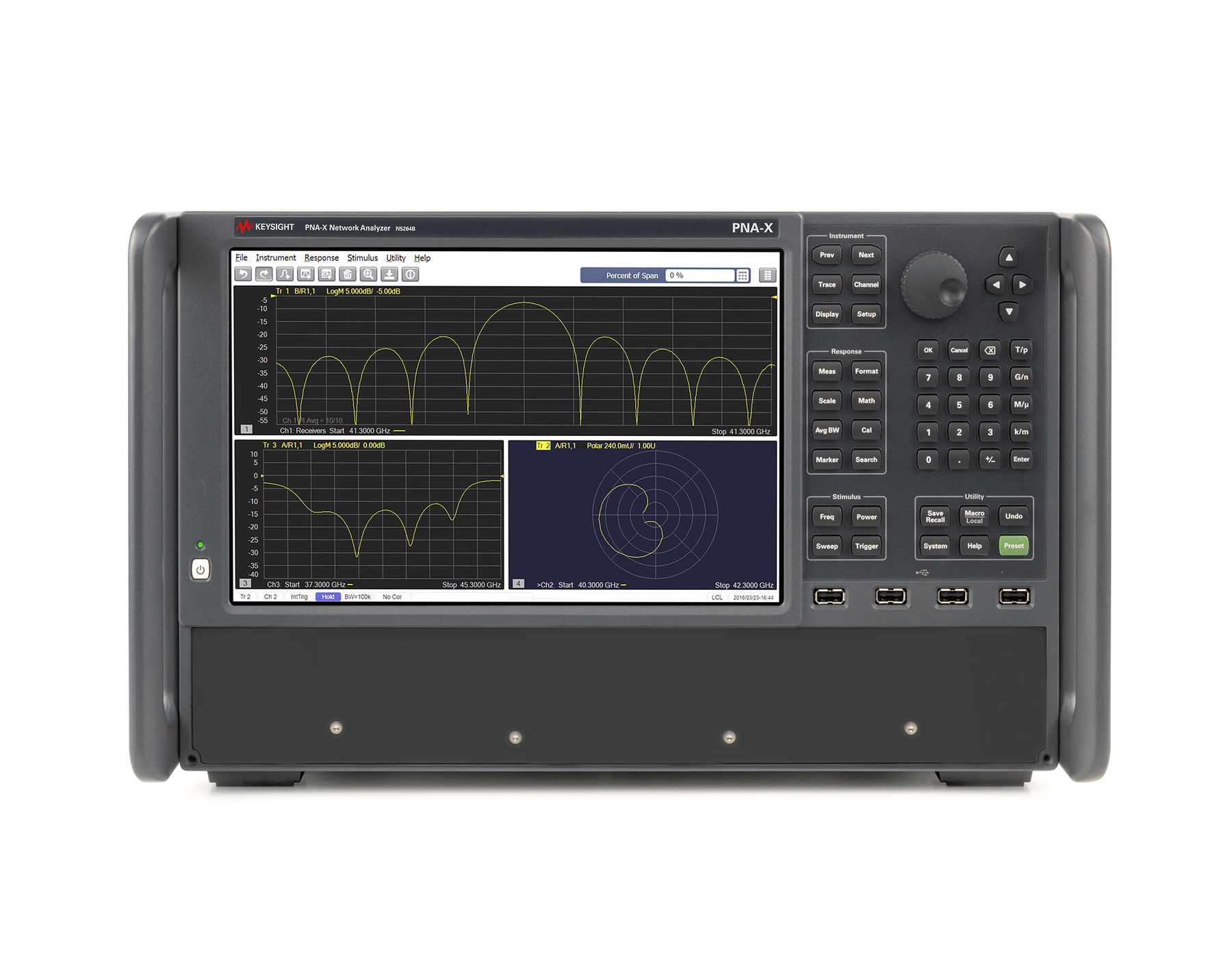
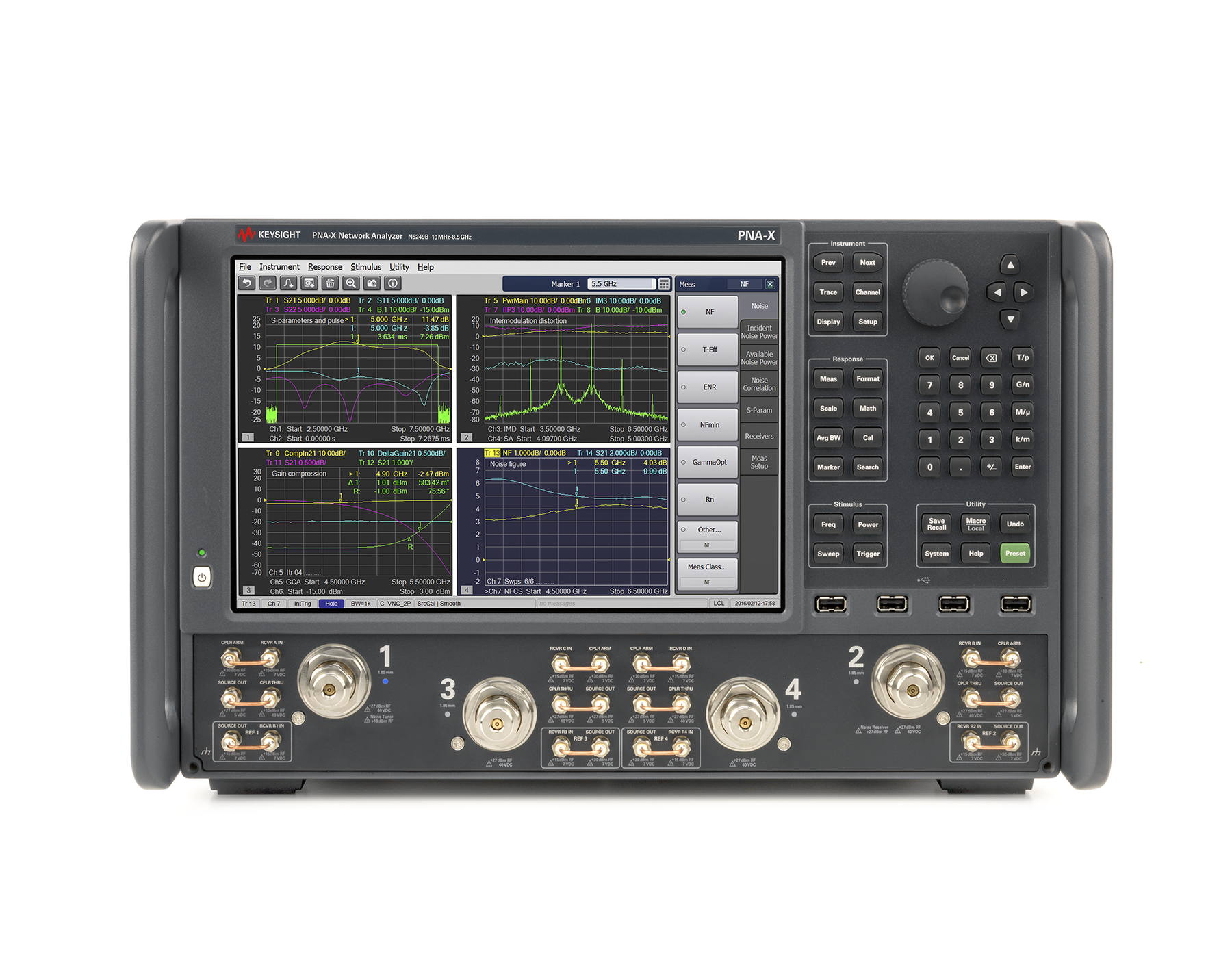
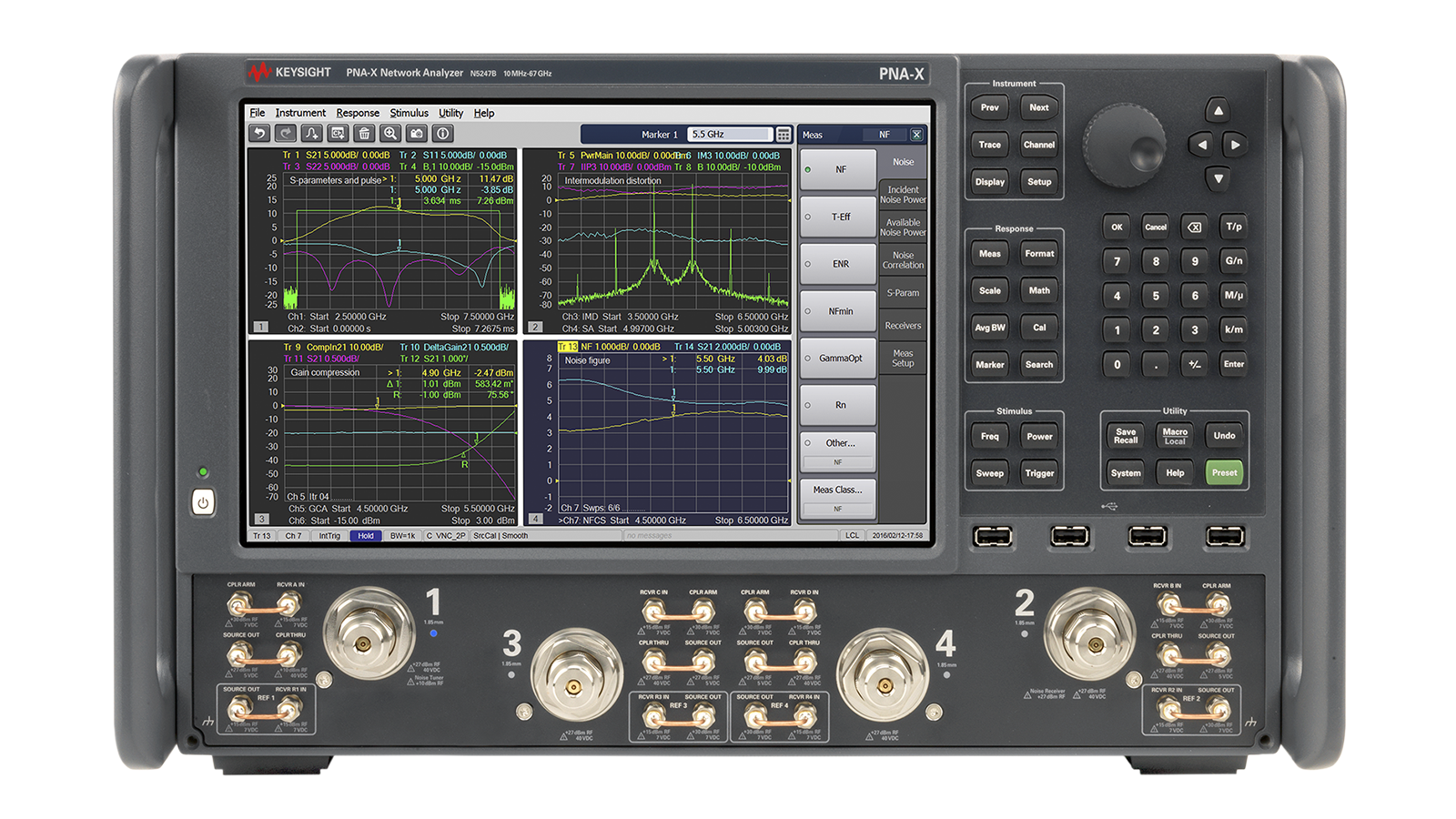
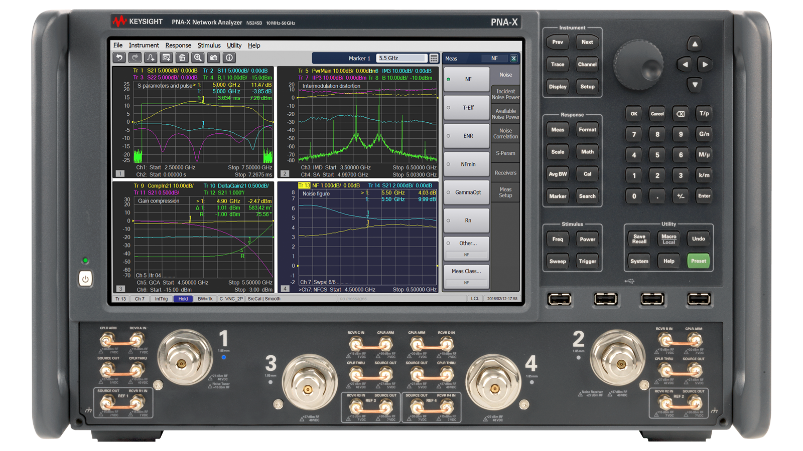




 粤公网安备44030902003758