是德科技 | KEYSIGHT
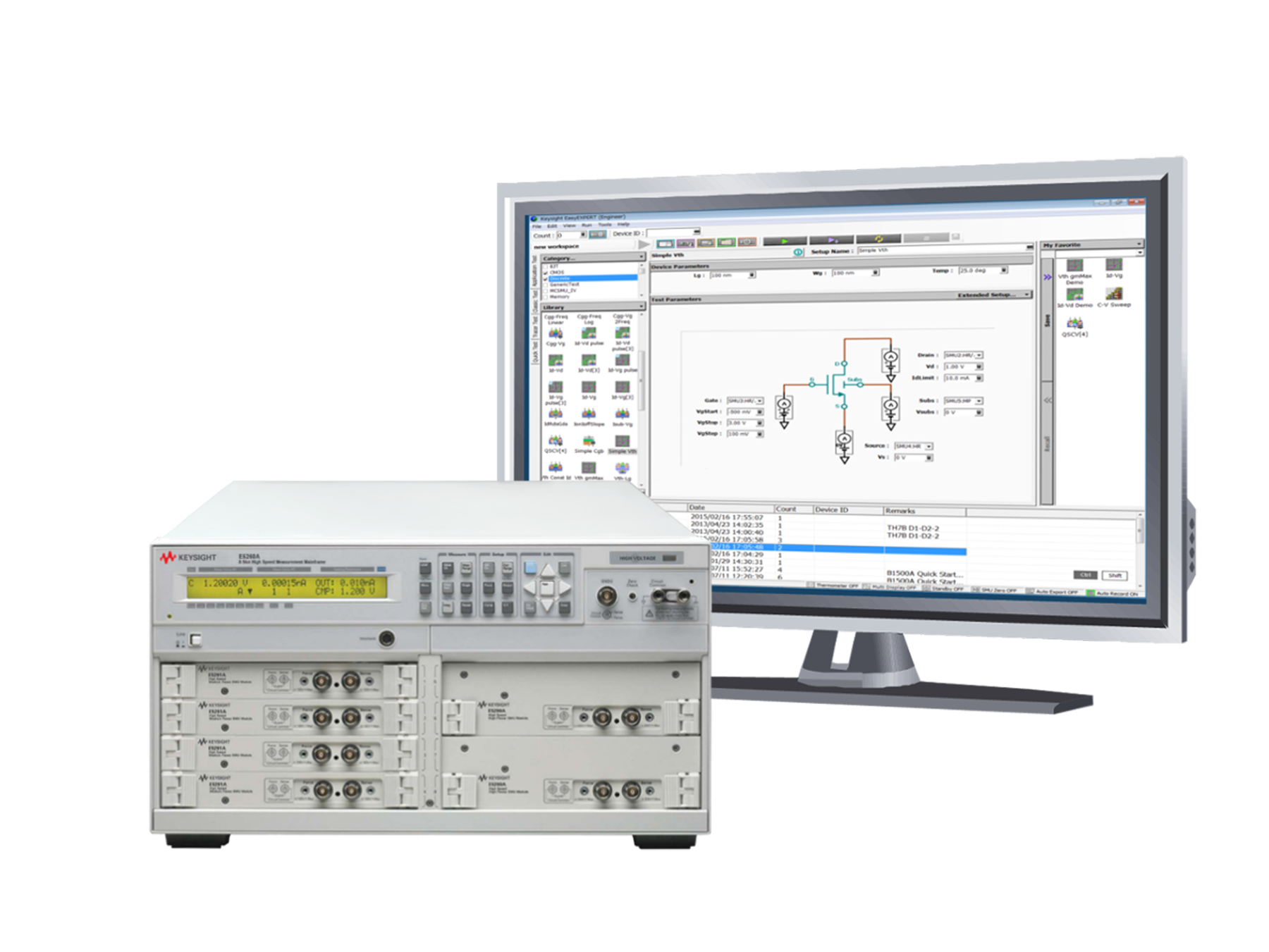
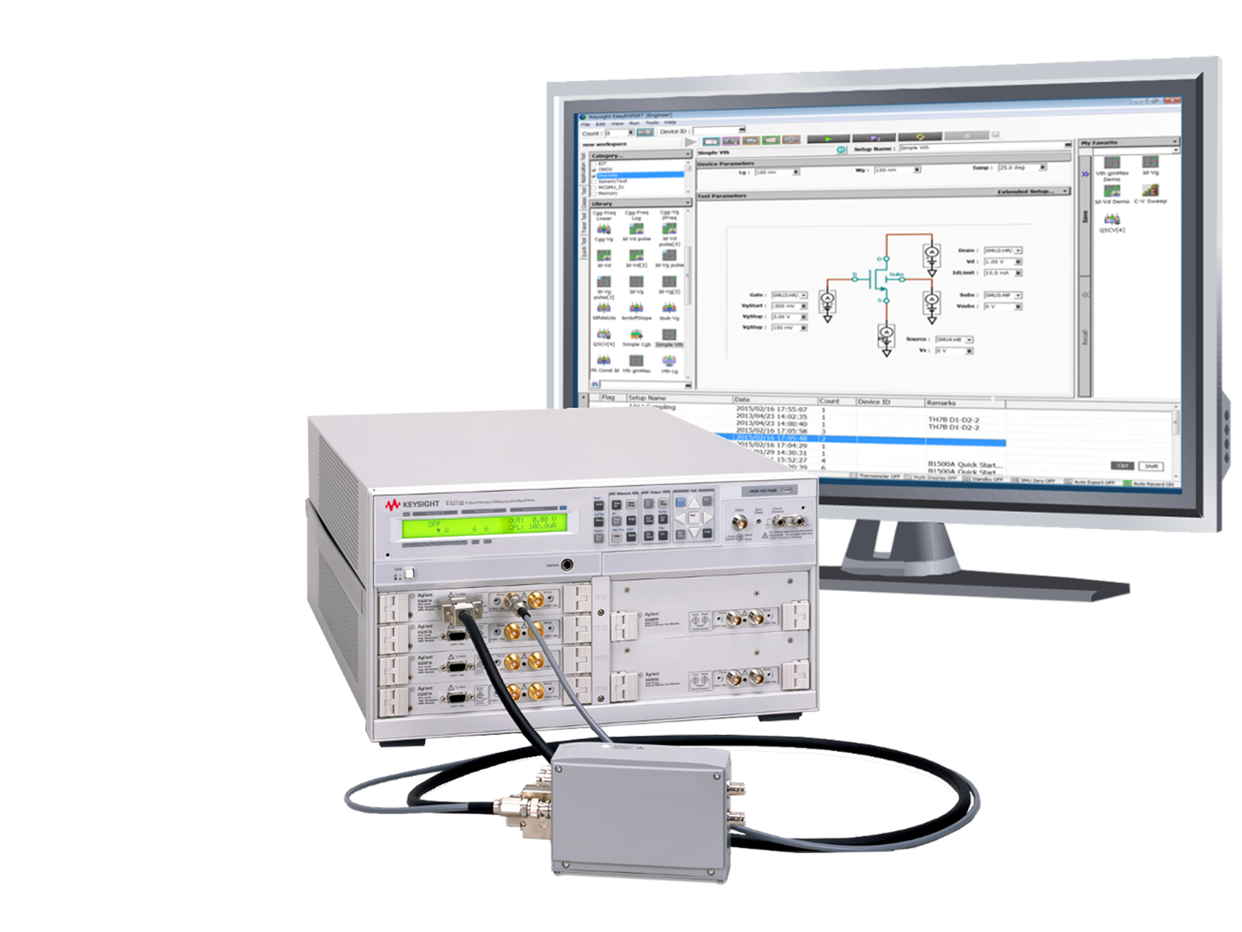
E5270B 分析仪 Upto8 详细指标
IV measurement systems for device characterization
一、E5270B Mainframe Specifications
Supported plug-In modules
The E5270B supports eight slots for plug-in modules.
– Ambient temperature change less than
± 1°C after auto calibration execution
– Measurement made within one hour after auto calibration execution
Integration time (high-resolution central ADC): 1 PLC (1 nA to 1A range)
20 PLC (100 pA range)
50 PLC (1 pA to 10 pA range)
– Calibration period
1 year
条件:Note: Using the HPSMU, MPSMU, and Atto Level HRSMU units, it is impossible to create a combination that exceeds the 80 watt limit.
The total module power consumption cannot exceed
80 W.
Pulse width
500 µsec to 2 s
Output voltage: 0 V
± 100 µV
For 1.6 A < IS ≤
2.0 A:
For 2.0 A < IS ≤
4.0 A:
Where IS is the current being sunk by the GNDU
Note: This document lists specifica - tions and supplemental information for the E5270B and its associated modules. The specifications are the
standards against which the E5270B
and its associated modules are tested. When the E5270B or any of its associated modules are shipped from the factory, they meet the specifica -
tions. The “supplemental” information and “typical” entries in the following specifications are not warranted, but provide useful information about the
条件:1. This is connected with the E5287A Atto Level HRSMU
Part number Description Slots occupied Range of operation Measure resolution
E5280B HPSMU 2 -200 V to 200 V, -1 A to 1 A 2 µV
10 fA
E5281B MPSMU 1 -100 V to 100 V, -100 mA to 100 mA 0.5 µV
10 fA
E5287A Atto Level HRSMU 1 -100 V to 100 V, -100 mA to 100 mA 0.5 µV
1 fA
E5288A1 Atto Sense and Switch Unit (ASU) – -100 V to 100 V, -100 mA to 100 mA 0.5 µV
0.1 fA
04 | Keysight | Precision IV Analyzer/8 Slot Precision Measurement Mainframe - Data Sheet
三、MPSMU (Medium 功率 SMU) 模块规格
Measure resolution Measure accuracy
1
条件:1. ± (% of output/measured value + offset voltage V)
2. 100 mA (Vo ≤ 20 V), 50 mA (20 V < Vo ≤ 40 V), Vo is the output voltage in volts.
3. 100 mA (Vo ≤ 20 V), 50 mA (20 V < Vo ≤ 40 V), 20 mA (40 V < Vo ≤ 100 V), Vo is the output voltage in volts.
Force accuracy
1 High speed ADC High resolution ADC Maximum
current ±0.5 V 25 µV 25 µV 0.5 µV ±(0.03 % + 350 µV) ±(0.03 % + 250 µV) ±(0.02 % + 250 µV) 100 mA ±2 V 100 µV 100 µV 2 µV ±(0.03 % + 900 µV) ±(0.03 % + 700 µV) ±(0.02 % + 700 µV) 100 mA ±5 V 250 µV 250 µV 5 µV ±(0.03 % + 2 mV) ±(0.03 % + 2 mV) ±(0.02 % + 1 mV)
100 mA
±20 V 1 mV 1 mV 20 µV ±(0.03 % + 4 mV) ±(0.03 % + 4 mV) ±(0.02 % + 2 mV)
100 mA
±40 V 2 mV 2 mV 40 µV ±(0.03 % + 7 mV) ±(0.03 % + 8 mV) ±(0.02 % + 3 mV)
2
±100 V 5 mV 5 mV 100 µV ±(0.04 % + 15 mV) ±(0.03 % + 20 mV) ±(0.03 % + 5 mV)
3
条件:4. ± (% of output/measured value + offset current A (fixed part determined by the output/measurement range + proportional part that is
multiplied by Vo) 5. Measurement accuracy when using either the high-speed ADC or the high-resolution ADC 6. 100 V (Io ≤ 20 mA), 40 V (20 mA < Io ≤ 50 mA), 20 V (50 mA < Io ≤ 100 mA), Io is the output current in amps. 7. Specified measurement resolution is limited by fundamental noise limits.
Force accuracy 1 Measure accuracy
1,2 Maximum
voltage ±1 nA 50 fA 50 fA 10 fA ±(0.5 %+3 pA+2 fA x Vo) ±(0.5 %+3 pA+2 fA x Vo) 100 V ±10 nA 500 fA 500 fA 10 fA ±(0.5 %+7 pA+20 fA x Vo) ±(0.5 %+5 pA+20 fA x Vo) 100 V ±100 nA 5 pA 5 pA 100 fA ±(0.12 %+50 pA+200 fA x Vo) ±(0.1 %+30 pA+200 fA x Vo)
100 V
±1 µA 50 pA 50 pA 1 pA ±(0.12 %+400 pA+2 pA x Vo) ±(0.1 %+200 pA+2 pA x Vo)
100 V
±10 µA 500 pA 500 pA 10 pA ±(0.12 %+5 nA+20 pA x Vo) ±(0.1 %+3 nA+20 pA x Vo)
100 V
±100 µA 5 nA 5 nA 100 pA ±(0.12 %+40 nA+200 pA x Vo) ±(0.1 %+20 nA+200 pA x Vo)
100 V
±1 mA 50 nA 50 nA 1 nA ±(0.12 %+500 nA+2 nA x Vo) ±(0.1 %+300 nA+2 nA x Vo)
100 V
±10 mA 500 nA 500 nA 10 nA ±(0.12 %+4 µA+20 nA x Vo) ±(0.1 %+2 µA+20 nA x Vo)
100 V
±100 mA 5 µA 5 µA 100 nA ±(0.12 %+50 µA+200 nA x Vo) ±(0.1 %+30 µA+200 nA x Vo)
3
Voltage range Power 0.5 V 20 x Ic (W) 2 V 20 x Ic (W) 5 V
20 x Ic (W)
20 < Vc ≤ 40
40 x Io (W)
40 < Vc ≤ 100
100 x Io (W)
Where Vc is the voltage compliance setting and Io is output current.
-20
-50
-100
Voltage (V)
05 | Keysight | Precision IV Analyzer/8 Slot Precision Measurement Mainframe - Data Sheet
Voltage/current compliance (limiting)
条件:The SMU can limit output voltage or current to prevent damaging the device under test.
Compliance accuracy: Same as the current (or voltage) set accuracy.
Maximum allowable cable resistance (Kelvin connection)
Voltage source output resistance
0.3 Ω typical (Force line, non-Kelvin connection)
≥ 1013 Ω
≥ 1013 Ω (1 nA range)
Current compliance setting accuracy (for opposite polarity)
For 1 nA to 10 nA ranges:
I setting accuracy
± 12 % of range
For 100 nA to 100 mA ranges:
I setting accuracy
± 2.5 % of range
For 1 nA to 10 nA ranges
1000 pF
For 100 nA to 10 mA ranges
10 nF
Maximum guard capacitance
900 pF
Maximum shield capacitance
5000 pF
Maximum guard offset voltage
± 3 mV
Voltage source
0.01 % of V range (rms)
Voltage source
0.03 % of V range
Current source
1 % of I range
范围 switching transient 噪声 (典型值, 滤波器 ON)
Measure resolution Measure accuracy
1
Force accuracy
1 High speed ADC High resolution
条件:1. ± (% of output/measured value + offset voltage V)
2. 1 A (Vo ≤20 V), 500 mA (20 V <Vo ≤40 V), Vo is the output voltage in volts.
3. 1 A (Vo ≤20 V), 500 mA (20 V <Vo ≤40 V), 125 mA (40 V <Vo ≤100 V), Vo is the output voltage in volts.
4. 1 A (Vo ≤20 V), 500 mA (20 V <Vo ≤40 V), 125 mA (40 V <Vo ≤100 V), 50 mA (100 V <Vo ≤200 V), Vo is the output voltage in volts.
Maximum current ±2 V 100 µV 100 µV 2 µV ±(0.03 % + 900 µV) ±(0.03 % + 700 µV) ±(0.02 % + 700 µV) 1 A ±20 V 1 mV 1 mV 20 µV ±(0.03 % + 4 mV) ±(0.03 % + 4 mV) ±(0.02 % + 2 mV)
1 A
±40 V 2 mV 2 mV 40 µV ±(0.03 % + 7 mV) ±(0.03 % + 8 mV) ±(0.02 % + 3 mV)
2
±100 V 5 mV 5 mV 100 µV ±(0.04 % + 15 mV) ±(0.03 % + 20 mV) ±(0.03 % + 5 mV)
3
±200 V 10 mV 10 mV 200 µV ±(0.045 % + 30 mV) ±(0.035 % + 40 mV) ±(0.035 % + 10 mV)
4
条件:5. (% of output/measured value + offset current A (fixed part determined by the output/measurement range + proportional part that is multiplied
by Vo) resolution (< pulse width) 6. Measurement accuracy when using either the high-speed ADC or the high-resolution ADC 7. 200 V (Io ≤ 50 mA), 100 V (50 mA < Io ≤ 100 mA) 8. 200 V (Io ≤ 50 mA), 100 V (50 mA < Io ≤ 125 mA), 40 V (125 mA < Io ≤ 500 mA), 20 V (500 mA < Io ≤ 1 A), Io is the output current in amps.
9. Specified measurement resolution is limited by fundamental noise limits
Force accuracy 1 Measure accuracy
1,2 Maximum
voltage ±1 nA 50 fA 50 fA 10 fA ±(0.5 %+3 pA+2 fA x Vo) ±(0.5 %+3 pA+2 fA x Vo) 200 V ±10 nA 500 fA 500 fA 10 fA ±(0.5 %+7 pA+20 fA x Vo) ±(0.5 %+5 pA+20 fA x Vo) 200 V ±100 nA 5 pA 5 pA 100 fA ±(0.12 %+50 pA+200 fA x Vo) ±(0.1 %+30 pA+200 fA x Vo)
200 V
±1 µA 50 pA 50 pA 1 pA ±(0.12 %+400 pA+2 pA x Vo) ±(0.1 %+200 pA+2 pA x Vo)
200 V
±10 µA 500 pA 500 pA 10 pA ±(0.12 %+5 nA+20 pA x Vo) ±(0.1 %+3 nA+20 pA x Vo)
200 V
±100 µA 5 nA 5 nA 100 pA ±(0.12 %+40 nA+200 pA x Vo) ±(0.1 %+20 nA+200 pA x Vo)
200 V
±1 mA 50 nA 50 nA 1 nA ±(0.12 %+500 nA+2 nA x Vo) ±(0.1 %+300 nA+2 nA x Vo)
200 V
±10 mA 500 nA 500 nA 10 nA ±(0.12 %+4 µA+20 nA x Vo) ±(0.1 %+2 µA+20 nA x Vo)
200 V
±100 mA 5 µA 5 µA 100 nA ±(0.12 %+50 µA+200 nA x Vo) ±(0.1 %+30 µA+200 nA x Vo)
3
±1 A 50 µA 50 µA 1 µA ±(0.5 %+500 µA+2 µA x Vo) ±(0.5 %+300 µA+2 µA x Vo)
4
06 | Keysight | Precision IV Analyzer/8 Slot Precision Measurement Mainframe - Data Sheet
Voltage/current compliance(limiting)
条件:The SMU can limit output voltage or current to prevent damaging the device under test.
Compliance accuracy: Same as the current (or voltage) set accuracy.
Maximum allowable cable resistance (Kelvin connection)
Force line: 10 Ω (I ≤
100 mA)
Force line: 1.5 Ω (100 mA < I ≤
1 A)
Sense line
10 Ω (All cases)
Voltage source output resistance
0.2 Ω typical (Force line, non-Kelvin connection)
Voltage range Power 2 V 20 x Ic (W) 20 V 20 x Ic (W) 40 V
40 x Ic (W)
20 < Vc ≤ 40
40 x Io (W)
40 < Vc ≤ 100
100 x Io (W)
100 < Vc ≤ 200
200 x Io (W)
Where Vc is the voltage compliance setting and Io is output current.
≥ 1013 Ω
≥ 1013 Ω (1 nA range)
Current compliance setting accuracy (for opposite polarity)
For 1 nA to 10 nA ranges:
I setting accuracy
± 12 % of range
For 100 nA to 1 A ranges:
I setting accuracy
± 2.5 % of range
For 1 nA to 10 nA ranges
1000 pF
For 100 nA to 10 mA ranges
10 nF
For 100 mA to 1 A ranges
100 µF
Maximum guard capacitance
900 pF
Maximum shield capacitance
5000 pF
Maximum guard offset voltage
± 1 mV
Voltage source
0.01 % of V
Voltage source
0.03 % of V range
Current source
1 % of I range
范围 switching transient 噪声 (典型值, 滤波器 ON)
Trigger out delay (pulsed measurements)
0 to 32.7 ms with 100 µs resolution (< pulse width)
07 | Keysight | Precision IV Analyzer/8 Slot Precision Measurement Mainframe - Data Sheet
1000
-50
-125
-500
-1000
-200 -100 -40 -20 20 40 100
200
Atto 电平 HRSMU 模块规格 ((不含) ASU)
Voltage range, resolution, and accuracy (Atto level HRSMU without ASU)
Measure resolution Measure accuracy
1
条件:1. ± (% of output/measured value + offset voltage)
2. 100 mA (Vo ≤ 20 V), 50 mA (20 V <Vo ≤ 40 V), Vo is the output voltage in volts.
3. 100 mA (Vo ≤ 20 V), 50 mA (20 V <Vo ≤ 40 V), 20 mA (40 V <Vo ≤ 100 V), Vo is the output voltage in volts.
Force accuracy
1 High speed ADC High resolution ADC Maximum
current ±0.5 V 25 µV 25 µV 0.5 µV ±(0.02 % + 150 µV) ±(0.01 % + 250 µV) ±(0.01 % + 150 µV) 100 mA ±2 V 100 µV 100 µV 2 µV ±(0.02 % + 400 µV) ±(0.01 % + 700 µV) ±(0.01 % + 200 µV) 100 mA ±5 V 250 µV 250 µV 5 µV ±(0.02 % + 750 µV) ±(0.01 % + 2 mV) ±(0.01 % + 250 µV)
100 mA
±20 V 1 mV 1 mV 20 µV ±(0.02 % + 3 mV) ±(0.01 % + 4 mV) ±(0.01 % + 1 mV)
100 mA
±40 V 2 mV 2 mV 40 µV ±(0.025 % + 6 mV) ±(0.015 % + 8 mV) ±(0.015 % + 2 mV)
2
±100 V 5 mV 5 mV 100 µV ±(0.03 % + 15 mV) ±(0.02% + 20 mV) ±(0.02 % + 5 mV)
3
Current range, resolution, and accuracy (Atto level HRSMU without ASU)
条件:4. ± (% of output/measured value + offset current A (fixed part determined by the output/measurement range + proportional part that is
multiplied by Vo) 5. Measurement accuracy when using either the high-speed ADC or the high-resolution ADC. 6. 100 V (Io ≤ 20 mA), 40 V (20 mA < Io ≤ 50 mA), 20 V (50 mA < Io ≤ 100 mA), Io is the output current in amps. 7. Minimum 10 aA display resolution at 10 pA range by 6 digits.
8. Specified measurement resolution is limited by fundamental noise limits.
Force accuracy 1 Measure accuracy
1,2 Maximum
voltage ±10 pA 5 fA 1 fA 1 fA ±(0.5 %+40 fA+10 aA x Vo) ±(0.5 %+15 fA+10 aA x Vo) 100 V ±100 pA 5 fA 5 fA 2 fA ±(0.5 %+120 fA+100 aA x Vo) ±(0.5 %+40 fA+100 aA x Vo) 100 V ±1 nA 50 fA 50 fA 10 fA ±(0.25 %+400 fA+1 fA x Vo) ±(0.25 %+300 fA+1 fA x Vo)
100 V
±10 nA 500 fA 500 fA 10 fA ±(0.25 %+4 pA+10 fA x Vo) ±(0.25 %+2 pA+10 fA x Vo)
100 V
±100 nA 5 pA 5 pA 100 fA ±(0.12 %+40 pA+100 fA x Vo) ±(0.1 %+20 pA+100 fA x Vo)
100 V
±1 µA 50 pA 50 pA 1 pA ±(0.12 %+400 pA+1 pA x Vo) ±(0.1 %+200 pA+1 pA x Vo)
100 V
±10 µA 500 pA 500 pA 10 pA ±(0.07 %+4 nA+10 pA x Vo) ±(0.05 %+2 nA+10 pA x Vo)
100 V
±100 µA 5 nA 5 nA 100 pA ±(0.07 %+40 nA+100 pA x Vo) ±(0.05 %+20 nA+100 pA x Vo)
100 V
±1 mA 50 nA 50 nA 1 nA ±(0.06 %+400 nA+1 nA x Vo) ±(0.04 %+200 nA+1 nA x Vo)
100 V
±10 mA 500 nA 500 nA 10 nA ±(0.06 %+4 µA+10 nA x Vo) ±(0.04 %+2 µA+10 nA x Vo)
100 V
±100 mA 5 µA 5 µA 100 nA ±(0.12 %+40 µA+100 nA x Vo) ±(0.1 %+20 µA+100 nA x Vo)
3
Voltage range Power 0.5 V 20 x Ic (W) 2 V 20 x Ic (W) 5 V
20 x Ic (W)
20 < Vc ≤ 40
40 x Io (W)
40 < Vc ≤ 100
100 x Io (W)
Where Vc is the voltage compliance setting and Io is output current.
Atto 电平 HRSMU(不含) ASU 测量和输出范围
-20
-50
-100
Voltage (V)
08 | Keysight | Precision IV Analyzer/8 Slot Precision Measurement Mainframe - Data Sheet
Voltage/current compliance(limiting)
条件:The SMU can limit output voltage or current to prevent damaging the device under test.
Current: ± 100 fA to
± 100 mA
Compliance accuracy: Same as the current (or voltage) set accuracy.
Maximum allowable cable resistance (Kelvin connection)
Voltage source output resistance
0.3 Ω typical (Force line, non-Kelvin connection)
≥ 1013 Ω
≥ 1013 Ω (1 nA range)
Current compliance setting accuracy (for opposite polarity)
For 10 pA to 10 nA ranges:
I setting accuracy
± 12 % of range
For 100 nA to 100 mA ranges:
I setting accuracy
± 2.5 % of range
For 10 pA to 10 nA ranges
1000 pF
For 100 nA to 10 mA ranges
10 nF
Maximum guard capacitance
900 pF
Maximum shield capacitance
5000 pF
Maximum guard offset voltage
± 3 mV
Voltage source
0.01 % of V
Current source
0.1 % of I range (rms)
Voltage source
0.03 % of V range
Current source
1 % of I range
范围 switching transient 噪声 (典型值, 滤波器 ON)
Trigger out delay (pulsed measurements)
0 to 32.7 ms with 100 µs resolution (< pulse width)
Atto 电平 HRSMU 模块规格 ((含) ASU)
Voltage range, resolution, and accuracy (Atto level HRSMU with ASU)
Measure resolution Measure accuracy
1
条件:1. ± (% of output/measured value + offset voltage)
2. 100 mA (Vo ≤ 20 V), 50 mA (20 V <Vo ≤ 40 V), Vo is the output voltage in volts.
3. 100 mA (Vo ≤ 20 V), 50 mA (20 V <Vo ≤ 40 V), 20 mA (40 V <Vo ≤ 100 V), Vo is the output voltage in volts.
Force accuracy
1 High speed ADC High resolution ADC Maximum
current ±0.5 V 25 µV 25 µV 0.5 µV ±(0.02 % + 150 µV) ±(0.01 % + 250 µV) ±(0.01 % + 150 µV) 100 mA ±2 V 100 µV 100 µV 2 µV ±(0.02 % + 400 µV) ±(0.01 % + 700 µV) ±(0.01 % + 200 µV) 100 mA ±5 V 250 µV 250 µV 5 µV ±(0.02 % + 750 µV) ±(0.01 % + 2 mV) ±(0.01 % + 250 µV)
100 mA
±20 V 1 mV 1 mV 20 µV ±(0.02 % + 3 mV) ±(0.01 % + 4 mV) ±(0.01 % + 1 mV)
100 mA
±40 V 2 mV 2 mV 40 µV ±(0.025 % + 6 mV) ±(0.015 % + 8 mV) ±(0.015 % + 2 mV)
2
±100 V 5 mV 5 mV 100 µV ±(0.03 % + 15 mV) ±(0.02% + 20 mV) ±(0.02 % + 5 mV)
3
09 | Keysight | Precision IV Analyzer/8 Slot Precision Measurement Mainframe - Data Sheet
Current range, resolution, and accuracy (Atto level HRSMU with ASU)
条件:1. ± (% of output/measured value + offset current A (fixed part determined by the output/measurement range + proportional part that is
multiplied by Vo) 2. Measurement accuracy when using either the high-speed ADC or the high-resolution ADC. 3. 100 V (Io ≤ 20 mA), 40 V (20 mA < Io ≤ 50 mA), 20 V (50 mA < Io ≤ 100 mA), Io is the output current in amps 4. Minimum 1 aA display resolution at 1 pA range by 6 digits.
5. Specified measurement resolution is limited by fundamental noise limits.
6. Measurements at lower range are affected strongly by vibrations and shocks. Do not place the environment of vibrations and shocks
Measure accuracy
1,2 Maximum
voltage ±1 pA 1 fA 100 aA 100 aA ±(1.8 %+15 fA) ±(1.8 %+12 fA) 100 V ±10 pA 5 fA 1 fA 400 aA ±(0.5 %+40 fA+10 aA x Vo) ±(0.5 %+15 fA+10 aA x Vo) 100 V ±100 pA 5 fA 5 fA 500 aA ±(0.5 %+120 fA+100 aA x Vo) ±(0.5 %+40 fA+100 aA x Vo)
100 V
±1 nA 50 fA 50 fA 10 fA ±(0.25 %+400 fA+1 fA x Vo) ±(0.25 %+300 fA+1 fA x Vo)
100 V
±10 nA 500 fA 500 fA 10 fA ±(0.25 %+4 pA+10 fA x Vo) ±(0.25 %+2 pA+10 fA x Vo)
100 V
±100 nA 5 pA 5 pA 100 fA ±(0.12 %+40 pA+100 fA x Vo) ±(0.1 %+20 pA+100 fA x Vo)
100 V
±1 µA 50 pA 50 pA 1 pA ±(0.12 %+400 pA+1 pA x Vo) ±(0.1 %+200 pA+1 pA x Vo)
100 V
±10 µA 500 pA 500 pA 10 pA ±(0.07 %+4 nA+10 pA x Vo) ±(0.05 %+2 nA+10 pA x Vo)
100 V
±100 µA 5 nA 5 nA 100 pA ±(0.07 %+40 nA+100 pA x Vo) ±(0.05 %+20 nA+100 pA x Vo)
100 V
±1 mA 50 nA 50 nA 1 nA ±(0.06 %+400 nA+1 nA x Vo) ±(0.04 %+200 nA+1 nA x Vo)
100 V
±10 mA 500 nA 500 nA 10 nA ±(0.06 %+4 µA+10 nA x Vo) ±(0.04 %+2 µA+10 nA x Vo)
100 V
±100 mA 5 µA 5 µA 100 nA ±(0.12 %+40 µA+100 nA x Vo) ±(0.1 %+20 µA+100 nA x Vo)
3
Voltage range Power 0.5 V 20 x Ic (W) 2 V 20 x Ic (W) 5 V
20 x Ic (W)
20 < Vc ≤ 40
40 x Io (W)
40 < Vc ≤ 100
100 x Io (W)
Where Vc is the voltage compliance setting and Io is output current. Atto level HRSMU with ASU measurement and output range
-20
-50
-100
Voltage (V)
10 | Keysight | Precision IV Analyzer/8 Slot Precision Measurement Mainframe - Data Sheet
Voltage/current compliance(limiting)
条件:The SMU can limit output voltage or current to prevent damaging the device under test.
Current: ± 10 fA to
± 100 mA
Compliance accuracy: Same as the current (or voltage) set accuracy.
Maximum allowable cable resistance (Kelvin connection)
Voltage source output resistance
0.3 Ω typical (Force line, non-Kelvin connection)
≥ 1013 Ω
≥ 1013 Ω (1 nA range)
Current compliance setting accuracy (for opposite polarity)
For 1 pA to 10 nA ranges:
I setting accuracy
± 12 % of range
For 100 nA to 100 mA ranges:
I setting accuracy
± 2.5 % of range
For 1 pA to 10 nA ranges
1000 pF
For 100 nA to 10 mA ranges
10 nF
Maximum guard capacitance
660 pF
Maximum shield capacitance
3500 pF
Maximum guard offset voltage: ± 4.2 mV (Iout ≤
100 µA)
Voltage source
0.01 % of V
Voltage source
0.03 % of V range
Current source
1 % of I range
范围 switching transient 噪声 (典型值, 滤波器 ON)
Trigger out delay (pulsed measurements)
0 to 32.7 ms with 100 µs resolution (< pulse width)
Maximum voltage 100 V: between AUX input and AUX common 100 V: between AUX input and circuit common
42 V: between AUX common and circuit common
Maximum current
0.5 A: between AUX input and force output
Band width (at –3 dB): <
30 MHz (AUX port)
11 | Keysight | Precision IV Analyzer/8 Slot Precision Measurement Mainframe - Data Sheet
条件:with the primary sweep channel as an additional voltage or current sweep source. Linear or log sweeps can be performed.
Outputs swept voltage or current, and measures dc voltage or current.
One channel can sweep current or voltage while up to eight channels can measure current or voltage. A second channel can be synchronized
1 ms resolution
100 µs resolution
Outputs swept voltage or current, and measures dc voltage or current.
Up to eight channels can sweep cur- rent or voltage and up to eight chan - nels can measure current or voltage. Linear or log sweeps
1 ms resolution
100 µs resolution
Outputs a voltage or current pulse and measures dc voltage or current.
Pulse width
500 µs to 100 ms
100 µs resolution
Pulse period
5 ms to 1 s (≥ pulse
width + 4 ms)
100 µs resolution
Outputs pulsed swept voltage or current, and measures dc voltage or current. A second channel can be programmed to output a staircase
sweep voltage or current synchro - nized with the pulsed sweep output.
Staircase 扫描(含) 脉冲 bias 测量模式
Outputs swept voltage or current, and measures dc voltage or current.
A second channel can be programmed to output a pulsed bias voltage or current. A third channel can be synchronized with the primary sweep
Outputs quasi-pulsed voltage and measures dc voltage or current.
Outputs and measure voltage or current by using linear search method.
Outputs and measure voltage or current by using binary search method.
The E5270B supports a time stamp
功能 utilizing 内部 quartz 时钟
条件:municate over the GPIB interface. In addition, input data can be passed to code sequences stored in program memory.
The E5270B mainframe contains
(volatile) memory that can be used to increase test measurement throughput. Program memory allows the storage of program code in the
E5270B, eliminating the need to com -
Maximum lines of storable code
40,000
Maximum number of program sequences
2,000
12 | Keysight | Precision IV Analyzer/8 Slot Precision Measurement Mainframe - Data Sheet
Trigger in/out synchronization pulses before and after setting and measur- ing dc voltage and current. Arbitrary trigger events can be masked or
– Start a measurement at each sweep step for a staircase sweep or multi channel sweep measurement
– Start the source output at each sweep step for a staircase sweep, pulsed sweep, staircase sweep with pulsed bias, or multi-channel
– Recover from a wait state
– Input level: TTL level, negative or positive edge trigger, or
– The end of a measurement is reached
条件:– The end of a measurement at each sweep step for a staircase sweep or multi channel sweep measurement is reached.
– Completion of the source output setup at each sweep step for a staircase sweep, pulsed sweep, staircase sweep with pulsed bias,
– Completion of the pulsed output setup for a pulsed spot measurement.
条件:an alternative to the BNC trigger-in and trigger-out lines to synchronize the E5270B with other instruments.
They can also be used as output and input ports for digital signals. The user can selectively assign pins to trigger mode or digital I/O mode.
Digital I/O 16 general-purpose digital I/O signals are available via a
25-pin DIN connector. These pins can be used as
Operating
0 m to 2,000 m (6,561 ft)
Storage
0 m to 4,600 m (15,092 ft)
Line frequency
47 Hz to 63 Hz
适用型号 EMC: IEC61326-1/EN61326-1
KC: RRA Notification amending
Radio Waves Act Article
58-2
适用型号安全: IEC61010-1/EN61010-1
CAN/CSA-C22.2
E5270B: 426 mm W x 235 mm H x
575
E5270B mainframe only
17 kg
– USB-GPIB interface (Keysight
82357B)
– GNDU to Kelvin adaptor (Keysight N1254A-100)
– CD-ROMs (EasyEXPERT install media, VXI plug&play driver and TIS library)
or 64 bit)
13 | Keysight | Precision IV Analyzer/8 Slot Precision Measurement Mainframe - Data Sheet
14 | Keysight | Precision IV Analyzer/8 Slot Precision Measurement Mainframe - Data Sheet
Keysight EasyEXPERT group+ Software
条件:allows you the option of storing test condition and measurement data automatically
able information is not lost and that measurements can be repeated at a later date.
environment that facilitate the development of complex testing algorithms.
Keysight EasyEXPERT group+ GUI based characterization software is available on
your PC to accelerate the characterization tasks. It supports efficient and repeatable
device characterization in the entire characterization process from measurement
setup and execution to analysis and data management either by interactive manual
operation or automation across a wafer in conjunction with a semiautomatic wafer
prober. EasyEXPERT group+ makes it easy to perform complex device characterization
immediately with the ready-to-use measurements (application tests) furnished, and
after each measurement in a unique built-in database (workspace), ensuring that valu -
Finally, EasyEXPERT has built-in analysis capabilities and a graphical programming
– Multiple measurement modes for quick setup and measurement execution
(application 测试, classic 测试, 和 quick 测试)
– Graphical display, automated analysis capabilities and data generation to
Excel and image for analysis and reporting
– Built-in database (workspace) records test data automatically and simplifies
the data management without numerous data files
– GUI-based control of the Keysight B2200A, B2201A and E5250A
– EasyEXPERT remote control function supports the remote measurement
execution of application tests that are created on GUI interactively, via the
– Data back capability and various data protection feature for shared usage
– Characterization environment is available on user’s PC as a personal and
portable analyzer environment. EasyEXPERT group+ can be installed on any
EasyEXPERT group+ comes with the application tests conveniently organized by device
type, application, and technology. You can easily edit and customize the furnished ap -
plication tests to fit your specific needs. Application tests are provided for the following
CMOS Transistor Id-Vg, Id-Vd, Vth, breakdown, etc
Bipolar Transistor Ic-Vc, diode, Gummel plot, breakdown, hfe, etc.
Nano Device Resistance, Id-Vg, Id-Vd, Ic-Vc, etc
条件:Reliability test NBTI/PBTI, electro migration, hot carrier injection, J-Ramp, TDDB, etc.
15 | Keysight | Precision IV Analyzer/8 Slot Precision Measurement Mainframe - Data Sheet
The application test mode provides application oriented point-
and-click test setup and execution. An application test can be se -
lected from the library by device type and desired measurement,
and then executed after modifying the default input parameters
as needed. Available application tests can be adapted to config -
The tracer test mode offers intuitive and interactive sweep control
using a rotary knob similar to a curve tracer. Just like an analog
curve tracer, you can sweep in only one direction (useful for R&D
device analysis) or in both directions (useful in failure analysis
applications). Test set ups created in tracer test mode can be
seamlessly and instantaneously transferred to classic test mode
A GUI-based Quick Test mode enables you to perform test se - quencing without programming. You can select, copy, rearrange and cut-and-paste any application tests with a few simple mouse clicks. Once you have selected and arranged your tests, simply
click on the measurement button to begin running an automated
Limited auto ranging, voltage/current compliance, power compliance, automatic sweep abort functions, self-test, and self-calibration
SMUs in “Standby” remain programmed to their specified output
value even as other units are reset for the next measurement.
条件:measurement. The function ceases as soon as these conditions end or when a measurement that does not use this function is started.
This function allows you to keep a source active between measurements. The source module will apply the specified bias between measurements when running classic tests inside an application test, in quick test mode, or during a repeated
This function subtracts the offset current from the current measurement raw data, and returns the result as the measure - ment data. This function is used to compensate the error factor (offset current) caused by the measurement path such as the
X-axis and up to eight Y-axes, linear and log scale, real time
Marker: Marker to min/max, interpolation, direct marker, and marker skip
Line: Two lines, normal mode, grad mode, tangent mode, and regression mode
Measurement data and calculated user function data are listed
in conjunction with sweep step number or time domain sampling
step number. Up to 20 data sets can be displayed.
Up to 20 user-defined parameters can be displayed on the
Automatic analysis function
On a graphics plot, the markers and lines can be automatically
located using the auto analysis setup. Parameters can be auto -
matically determined using automatic analysis, user function, and
Up to 20 user-defined analysis functions can be defined using
Measured data, pre-defined variables, and read out functions can
The read out functions are built-in functions for reading various
条件:X-Y graph plot can be printed or stored as image data to clipboard or mass storage device. (File type: bmp, gif, png, emf).
Graph and list data can be exported to Excel.
16 | Keysight | Precision IV Analyzer/8 Slot Precision Measurement Mainframe - Data Sheet
Up to 20 user-defined functions can be defined using
条件:base e), mavg (moving average), max,min, sqrt, trigonometric function, inverse trigonometric function, and so on.
+, -, *, /, ^, abs (absolute value), at (arc tangent), avg (averaging),
cond (conditional evaluation), delta, diff (differential), exp (expo -
nent), integ (integration), lgt (logarithm, base
10), log (logarithm
Keyboard constants are stored in memory as follows: q: Electron charge, 1.602177E-19 C k: Boltzman’s constant
1.380658E-23 ε (e): Dielectric constant of vacuum
8.854188E-12
The following unit symbols are also available on the keyboard:
a (10-18), f (10-15), p (10-12), n (10-9),
u or μ (10-6), m (10-3), k (103), M (106),
G (109), T (1012) , P (1015)
EasyEXPERT group+ supports the built-in database called
条件:“workspace”. Workspaces are created on a HDD, and they enable to manage and access all the measurement related data without handling numerous files. Every workspace supports the following features:
– Access to measurement capabilities and data stored in the workspace.
– Save/Import/Export measurement settings and data (application library, measurement settings, my favorite setup, and measurement data)
– Recall the setup for measurement reproduction and data for analysis
Precision 电流 - 电压分析仪 Series
Discontinued Advanced Device Analyzer Precision IV Analyzer Economic IV
I/V Sweep Yes Yes Yes Yes Yes Yes1
GUI based switching matrix control
Yes2 - Yes2 Yes2 Yes2 Yes2
Oscilloscope view Yes3 Yes3 - - - -
External instrument driver support
LCR meter (4284A/E4980A)
Pulse Generator (81110A) Yes Yes Yes Yes Yes Yes
DVM (3458A) Yes Yes Yes Yes Yes Yes
Prober control in Quick Test mode Yes4 Yes4 Yes4 Yes4 Yes4 Yes4
Firmware requirement A.04.00 or
later5
A.04.00 or
later5
B.01.10 or
条件:later 1. PGU and VSU/VMU are supported. Differential voltage measurement of VMU is not supported. 2. B2200/01A and E5250A (with E5252A cards) are supported 3. Only available for supported modules.
4. Cascade Microtech Sumit 12000/S300 (Nucleus), Cascade Microtech (Suss MicroTec) PA200/PA300, and Vector Semiconductor VX-2000/VX-3000
5. The latest firmware version is strongly recommended to take full advantage of measurement capabilities.
B.01.10 or
later 1.0 or later HOSTC
03.08 or later
17 | Keysight | Precision IV Analyzer/8 Slot Precision Measurement Mainframe - Data Sheet
EasyEXPERT group+ supported instruments and prerequisites
Supported instruments and features
18 | Keysight | Precision IV Analyzer/8 Slot Precision Measurement Mainframe - Data Sheet
以上指标摘自厂家官方数据手册,完整定义、测试条件与保证值口径以手册为准。完整指标、测试条件与定义口径请见产品页「软件和手册 | 白皮书」栏目中的官方数据手册。
是德科技 | KEYSIGHT · onetest 仪器资源库



 客服






 粤公网安备44030902003758