

完整技术指标
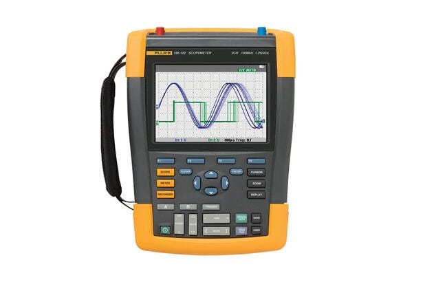
Oscilloscope Models
·
– 2:190-062
– 2:190-102
– 2:190-202
– 2:190-502
– 4:190-104
– 4:190-204
– 4:190-504
Vertical deflection
· Bandwidth
– 2:60 MHz
– 2:100 MHz
– 2:200 MHz
– 2:500 MHz
– 4:100 MHz
– 4:200 MHz
– 4:500 MHz
· Rise time
– 2:5.8 ns
– 2:3.5 ns
– 2:1.7 ns
– 2:0.7 ns
– 4:3.5 ns
– 4:1.7 ns
– 4:0.7 ns
· Number of scope inputs
– 2 input channels plus external trigger;4 input channels
· Channel architecture
– All inputs fully insulated from each other and from ground. Inputs may be activated in any combination.
· Input coupling:AC or DC, with ground level indicator
· Input sensitivity
– With 10:1 probe, 20 mV to 1000 V/div With 100:1 probe, 200 mV to 10 kV/div Direct (1:1), 2 mV to 100 V/div
· Bandwidth limiter:20 MHz and 10 kHz
· Polarity:Normal, Inverted, Variable
· Input voltage
– CAT III 1000 V/CAT IV 600 V rated, see General specifications for further details
· Vertical resolution:8 bit
· Accuracy at 4 s to 10 μs/div
– 5 mV/div to 100 V/div, ±(1.5 % + 6 counts) 2 mV/div, ±(1.5 % + 10 counts)
· Accuracy at 4 s to 10 μs/div 5 mV/div to 100 V/div, ±(1.5 % + 6 counts) 2 mV/div, ±(1.5 % + 10 counts)
– 4:Input impedance
– 4:1 MΩ (± 1 %) // 15 pF (± 2.25 pF)
Horizontal
· Maximum real- time sample rate (sampled simultaneously)
– 2:625 MS/s (each channel)
– 2:1.25 GS/s (each channel)
– 2:2.5 GS/s (each channel)
– 2:5 GS/s (single channel) or 2.5 GS/s (dual channel)
– 4:1.25 GS/s (each channel)
– 4:2.5 GS/s (2ch) 1.25 GS/s (4ch)
– 4:5 GS/s (single ch) or 2.5 GS/s (2ch) or 1.25 GS/s (4ch)
· Maximum real- time sample rate (sampled simultaneously) 625 MS/s (each channel) 1.25 GS/s (each channel)
– 2:2.5 GS/s (each channel)
– 2:5 GS/s (single channel) or 2.5 GS/s (dual channel)
– 2:1.25 GS/s (each channel)
– 2:2.5 GS/s (2ch) 1.25 GS/s (4ch)
– 4:5 GS/s (single ch) or 2.5 GS/s (2ch) or 1.25 GS/s (4ch)
– 4:Record length
– 4:Up to 10, 000 samples per channel
· Maximum real- time sample rate (sampled simultaneously) 625 MS/s (each channel) 1.25 GS/s (each channel) 2.5 GS/s (each channel) 5 GS/s (single channel) or 2.5 GS/s (dual channel) 1.25 GS/s (each channel) 2.5 GS/s (2ch) 1.25 GS/s (4ch) 5 GS/s (single ch) or 2.5 GS/s (2ch) or 1.25 GS/s (4ch) Time base range
– 2:10 ns/div to 4 s/div
– 2:5 ns/div to 4 s/div
– 2:2 ns/div to 4 s/div
– 2:1 ns/div to 4 s/div
– 4:5 ns/div to 4 s/div
– 4:2 ns/div to 4 s/div
– 4:1 ns/div to 4 s/div
· Time base in a 1-2-4-sequence Slower time/division settings using ScopeRecord Roll mode (see ‘Recorder mode’)
– 4:Maximum record length
– 4:Time base range
– 4:10, 000 samples per channel in scope mode 30, 000 points per channel in ScopeRecord Roll mode (see ‘Recorder mode’)
· Timing accuracy
– ± (0.01 % of reading + 1 pixel)
– Time base range
– 10, 000 samples per channel in scope mode 30, 000 points per channel in ScopeRecord Roll mode (see ‘Recorder mode’)
· Glitch capture:8 ns (10 µs/div to 2 min/div)
Display and acquisition
· Display
– 133 mm x 90 mm (5.3 in x 3.5 in) full-color high brightness LCD
· Display modes
– Any combination of channels
– average on/off
– replay.
· Visible screen width:12 divisions horizontally in scope mode
· Digital persistence modes
– Off, short, medium, long, infinite and envelope mode
· Waveform mathematics
– One (190-xx2) or two (190-x04) mathematical operations on 2 input channels (A and B, C and D): add, subtract, multiply
– X-Y-mode
– Frequency Spectrum using FFT
· Acquisition modes
– Normal, Averaged, Auto, Single Shot, ScopeRecord roll, glitch capture, waveform compare with automatic “Pass/Fail testing”; Replay
Trigger and delay
· Source
– Input A, B or External (via meter input);Input A, B, C or D
· Modes
– Automatic, Edge, Pulse Width, N-Cycle, External (190-xx2)
· Connect-and- View
– Advanced automatic triggering that recognizes signal patterns, automatically sets up and continuously adjusts triggering, time base and amplitude. Automatically displays stable waveforms of complex and dynamic signals like motor drive and control signals. Can be switched off if preferred.
· Pulse width triggering (on channel A)
– Pulse width qualified by time Allows for triggering t, =t, ≠ t, where t is selectable in minimum steps of 0.01 div or 50 ns
· Time delay
– 1 full screen of pre-trigger view or up to 100 screens (=1, 200 divisions) of post-trigger delay
· Dual slope triggering
– Triggers on both rising and falling edges alike
· N-cycle triggering
– Triggers on N-th occurrence of a trigger event; N to be set in the range 2 to 99
Automatic capture of 100 screens
· Replay
– Manual or continuous replay. Displays the captured 100 screens as a “live” animation, or under manual control. Each screen has date and time-stamp.
· Replay storage
– Ten sets of 100 screens each can be saved internally for later recall and analysis. Direct storage of additional sets on external flash memory drive through USB host port.
Shows frequency content of oscilloscope waveform using Fast Fourier Transform
· Window:Automatic, Hamming, Hanning or None
· Automatic window
– Digitally re-samples acquired waveform to get optimum frequency resolution in FFT resultant.
· Vertical scale:Linear/Logarithmic (in volts or amps)
· Frequency axis
– Frequency range automatically set as a function of timebase range of oscilloscope
Waveform compare and pass/fail testing
· Waveform compare
– Provides storage and display of a reference waveform for visual comparison with newly acquired waveforms. Reference is derived from an acquired waveform and can be modified in the oscilloscope.
· Pass/Fail testing
– In waveform compare mode, the oscilloscope can be set up to store only matching